Chant
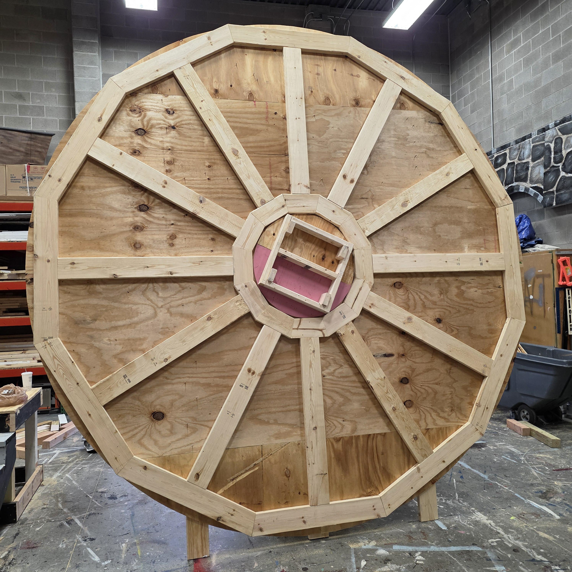
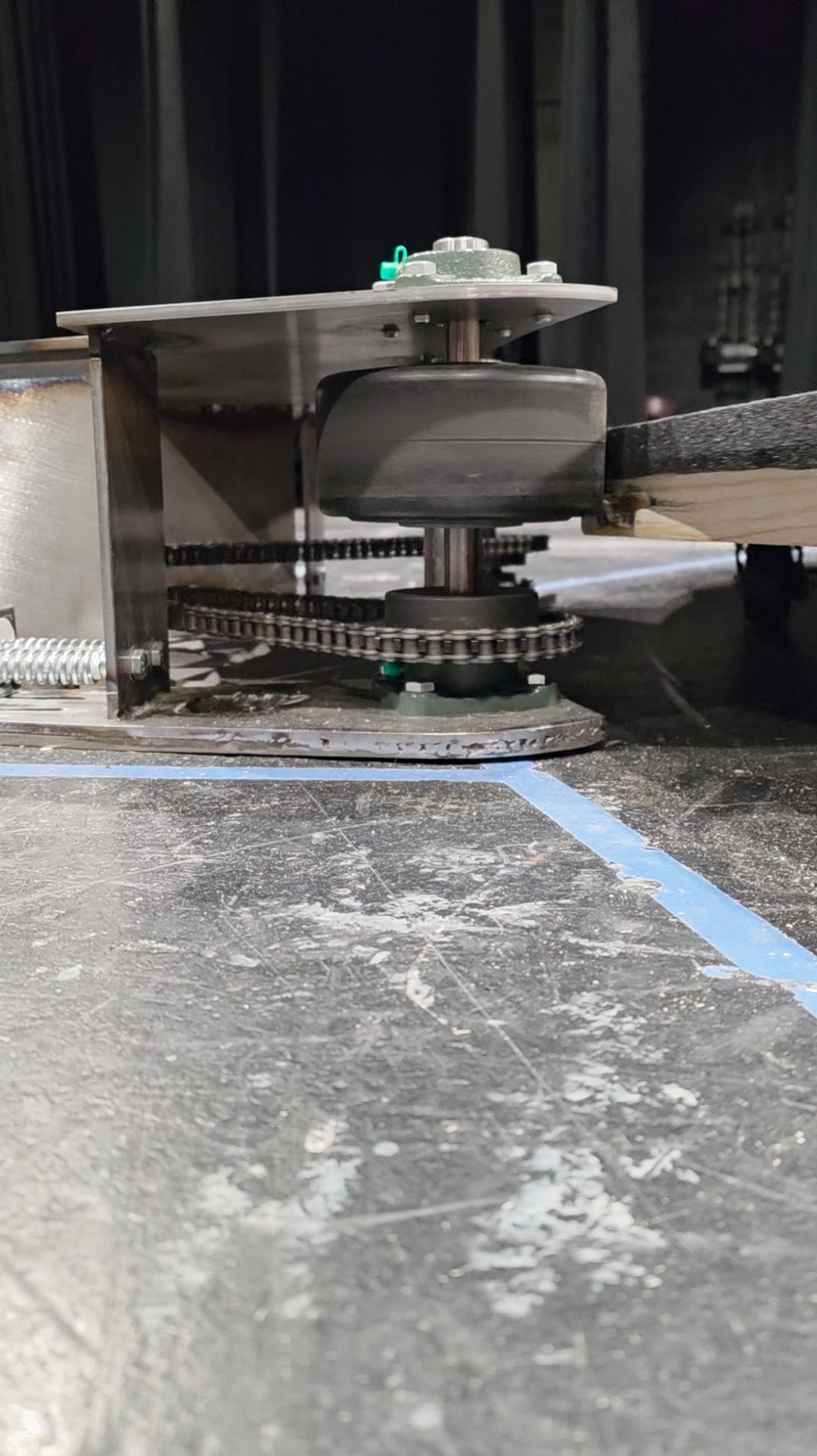
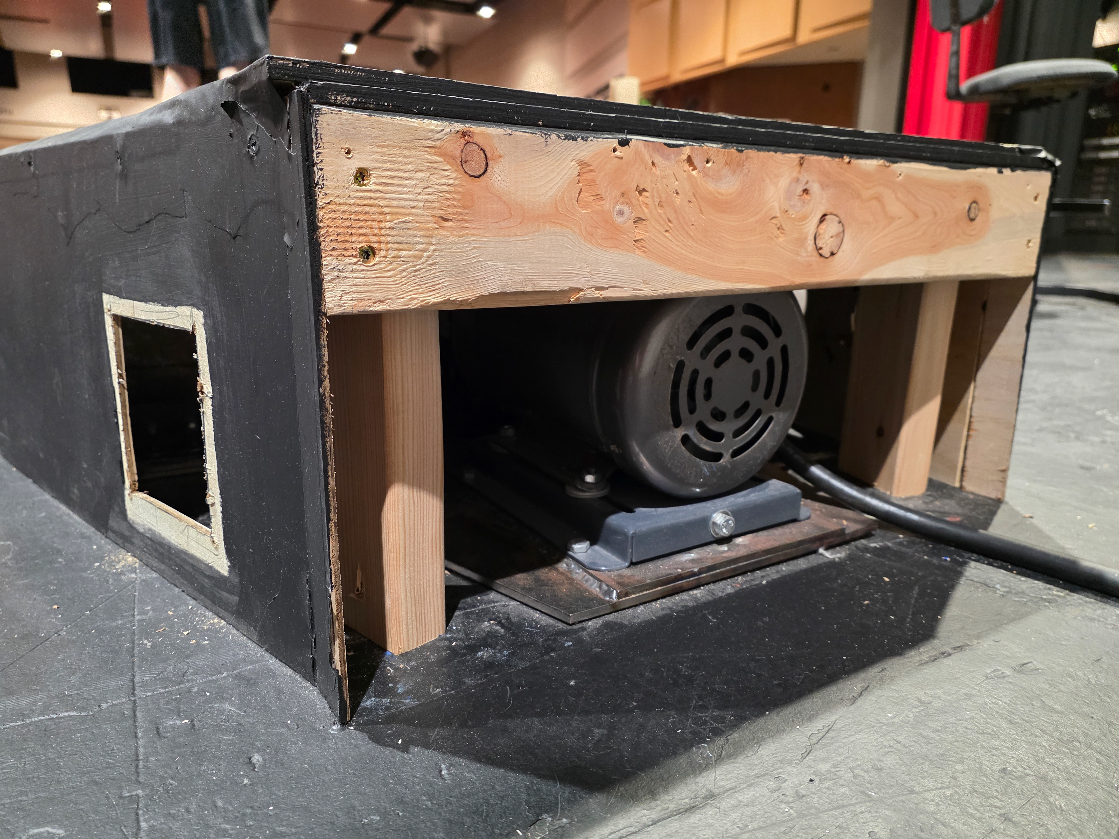
Underside
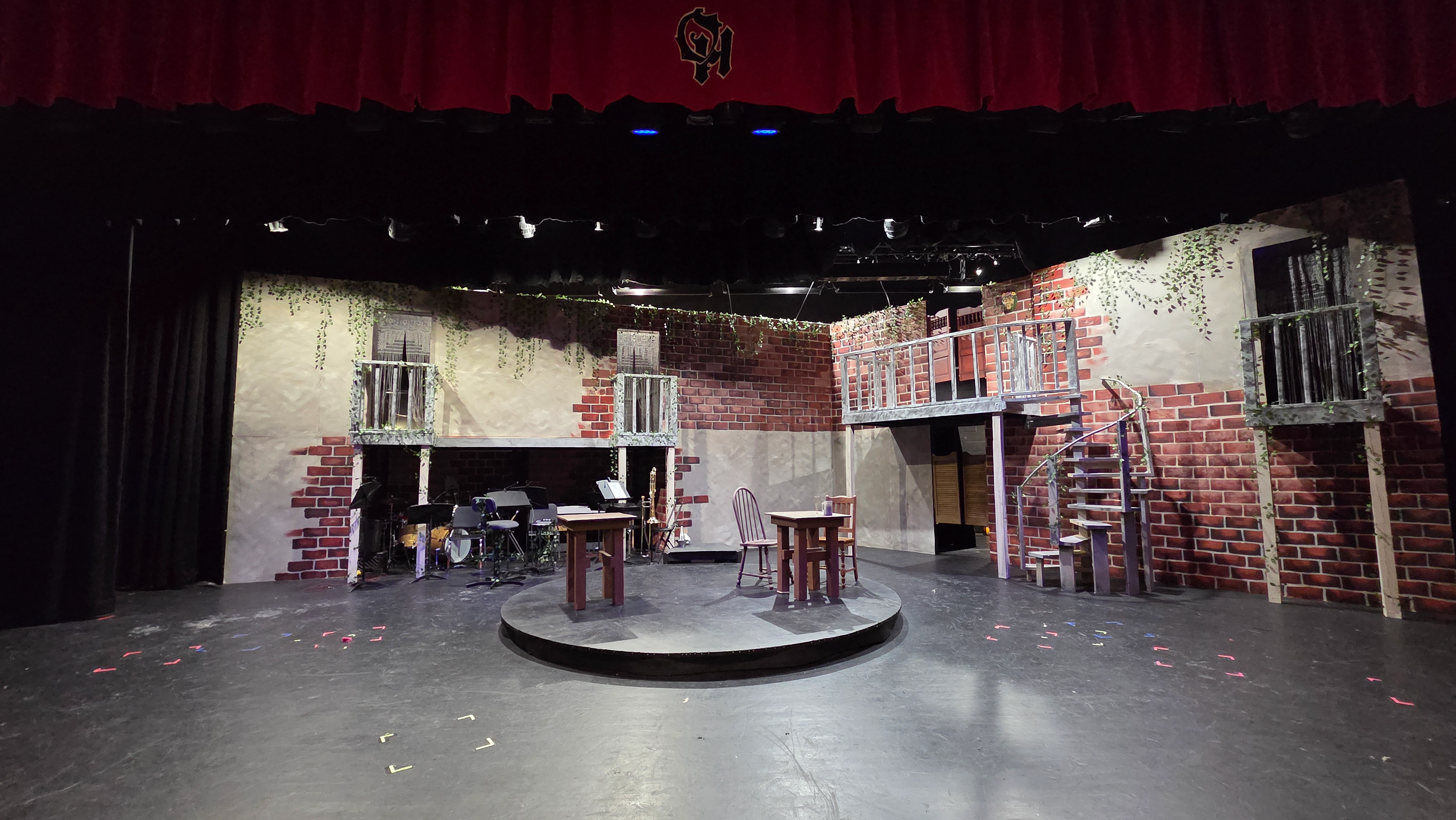
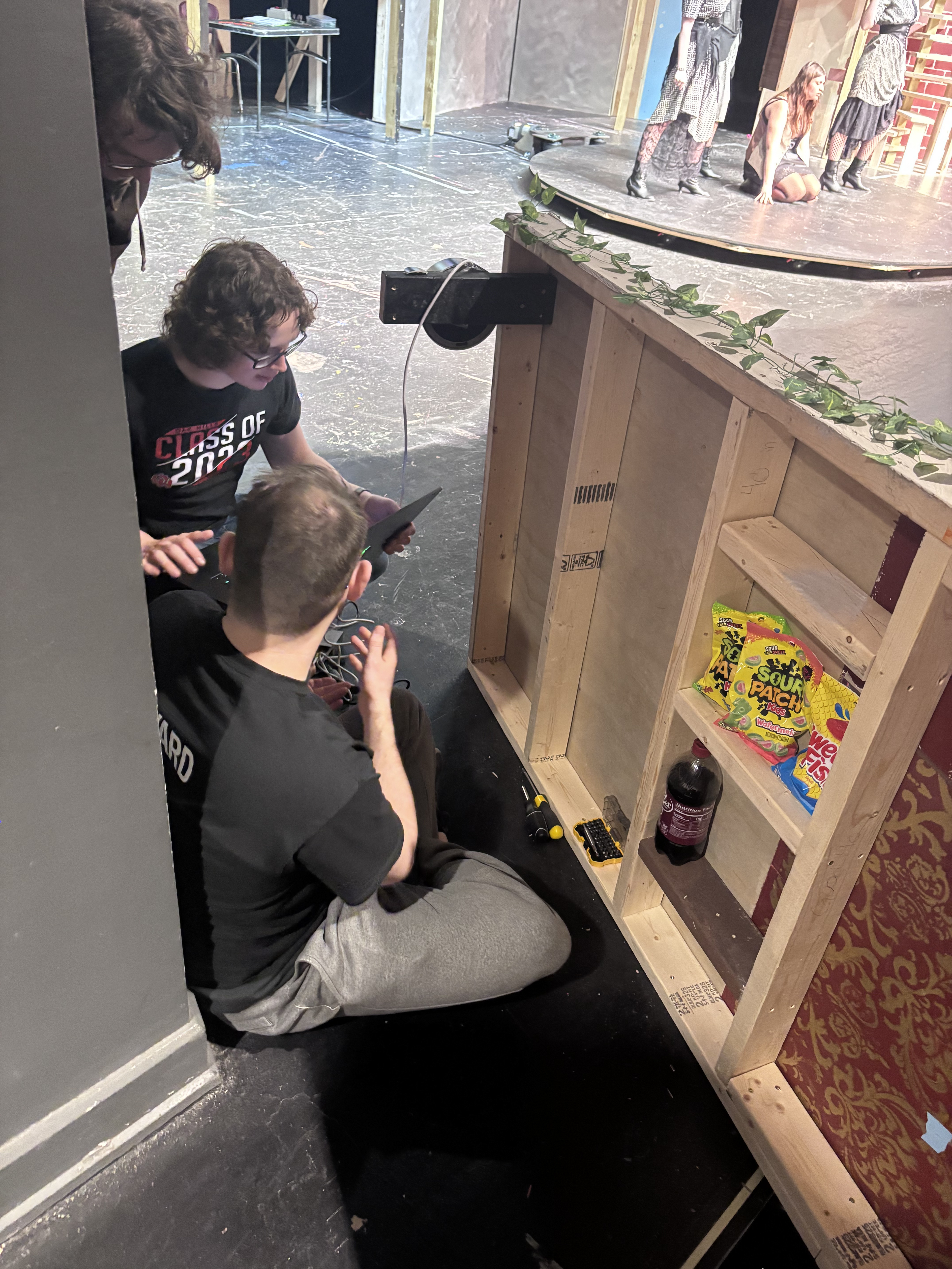
Full Stage Integration
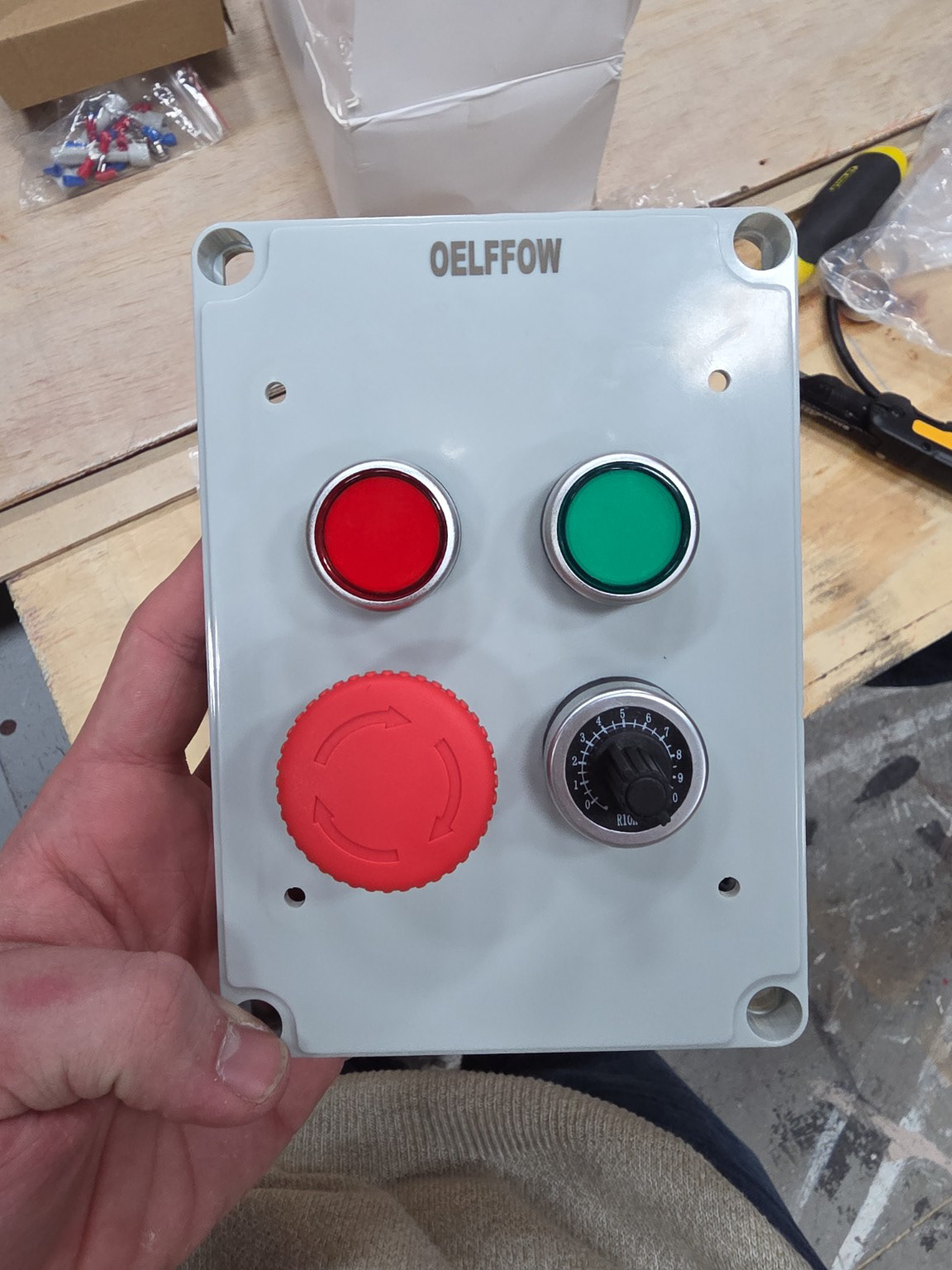
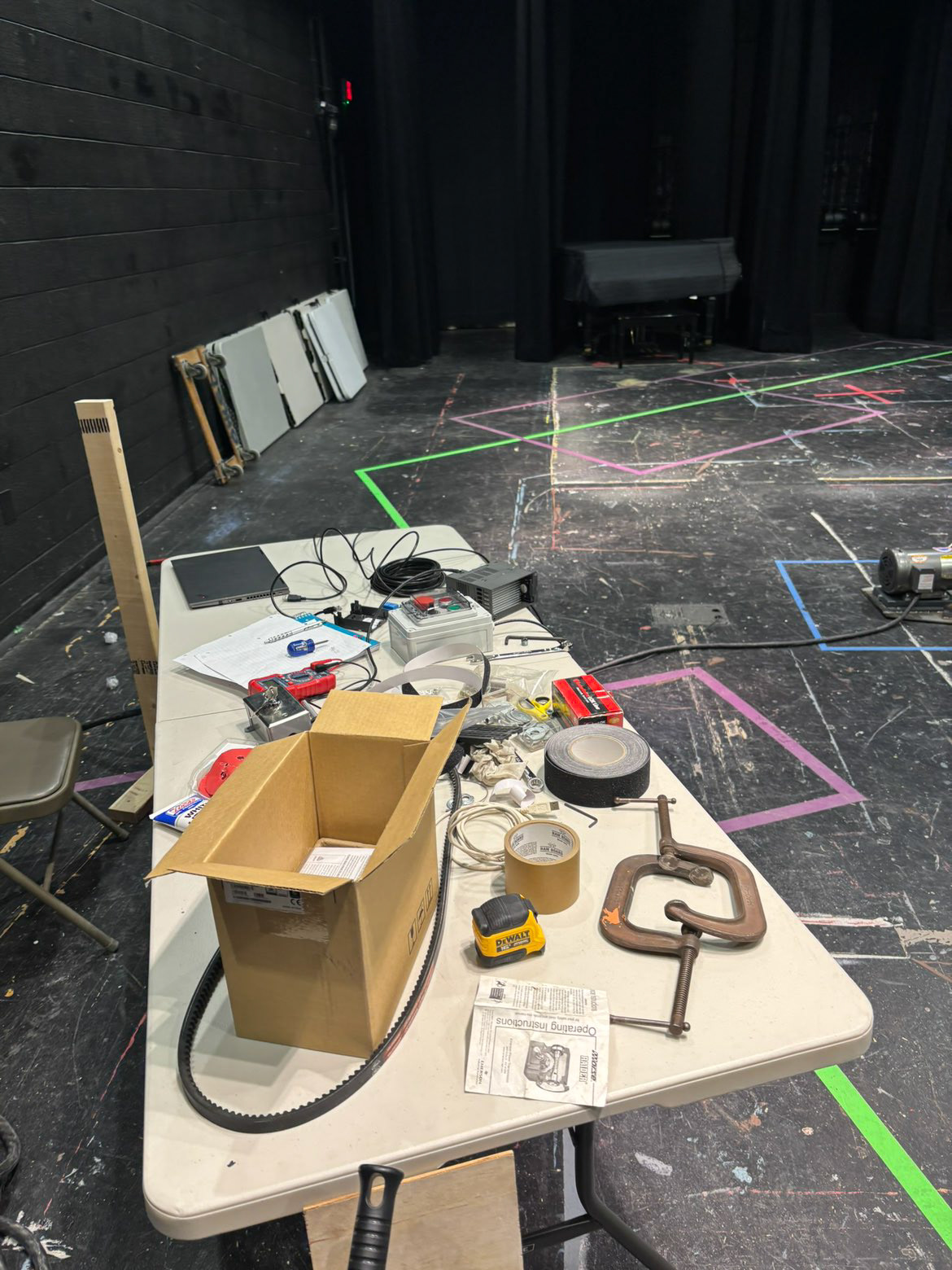
Controller
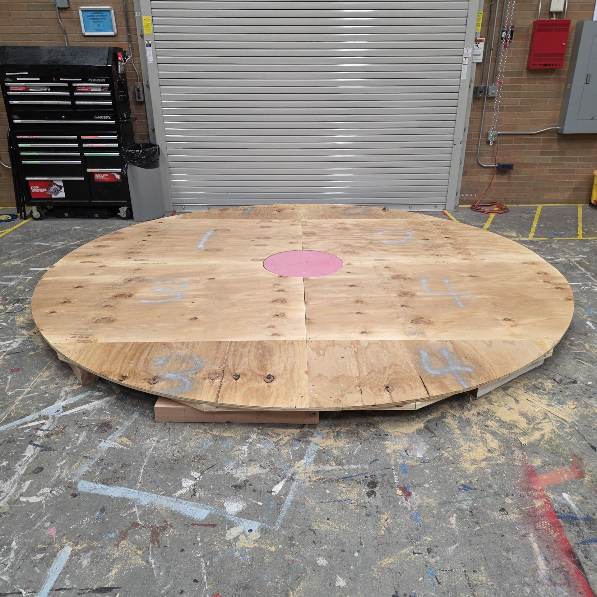
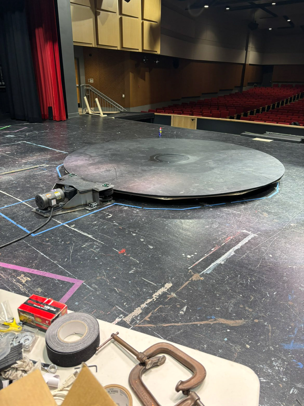
Revolve Loaded and Operational
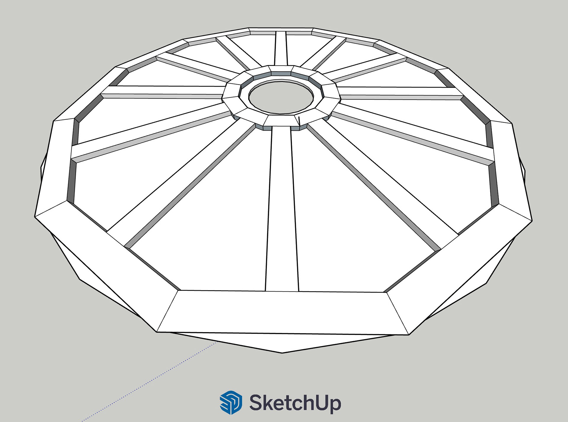
Early CAD Design on SketchUp
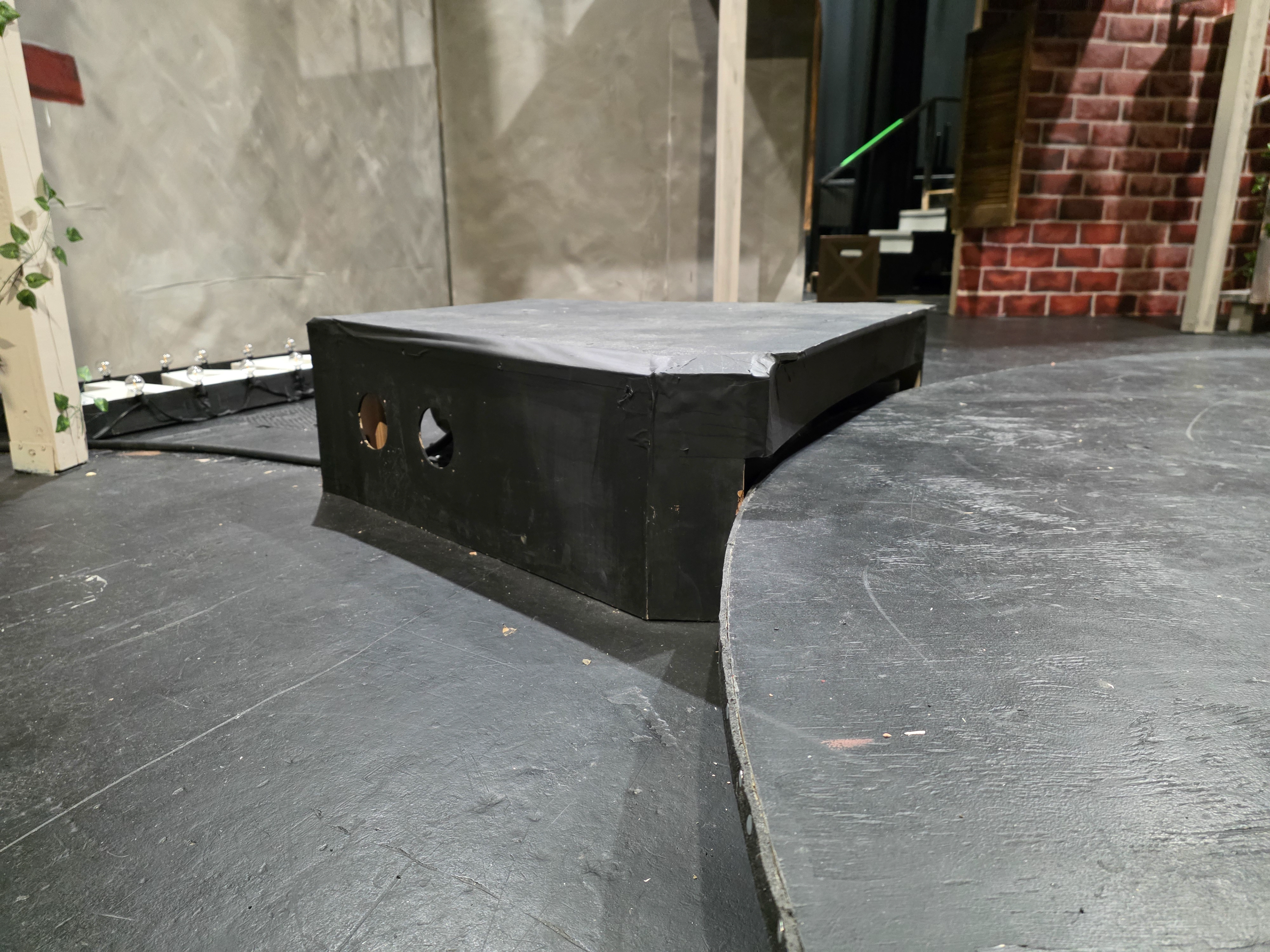
Fully Covered Structure
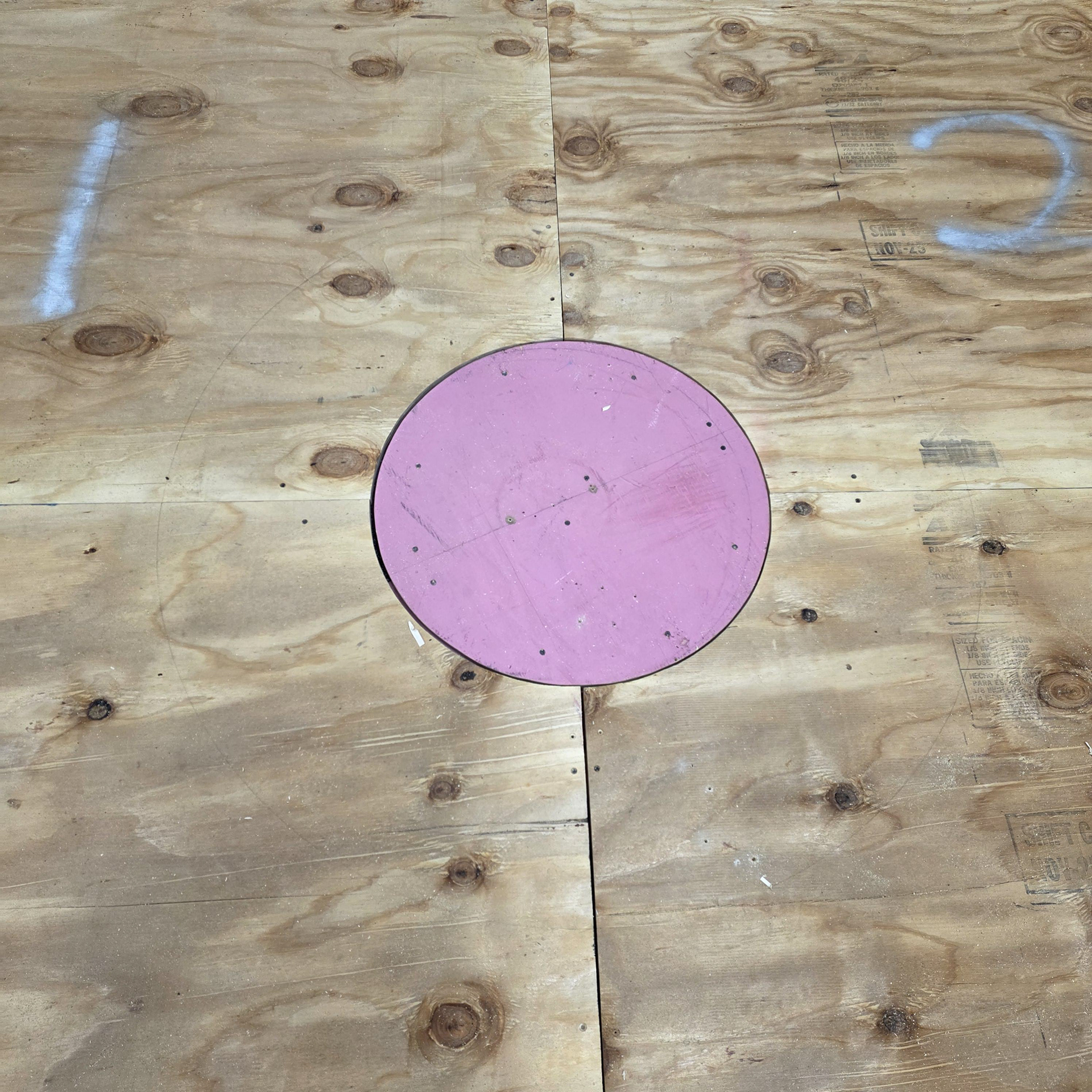
Center Platform

Framed Underside
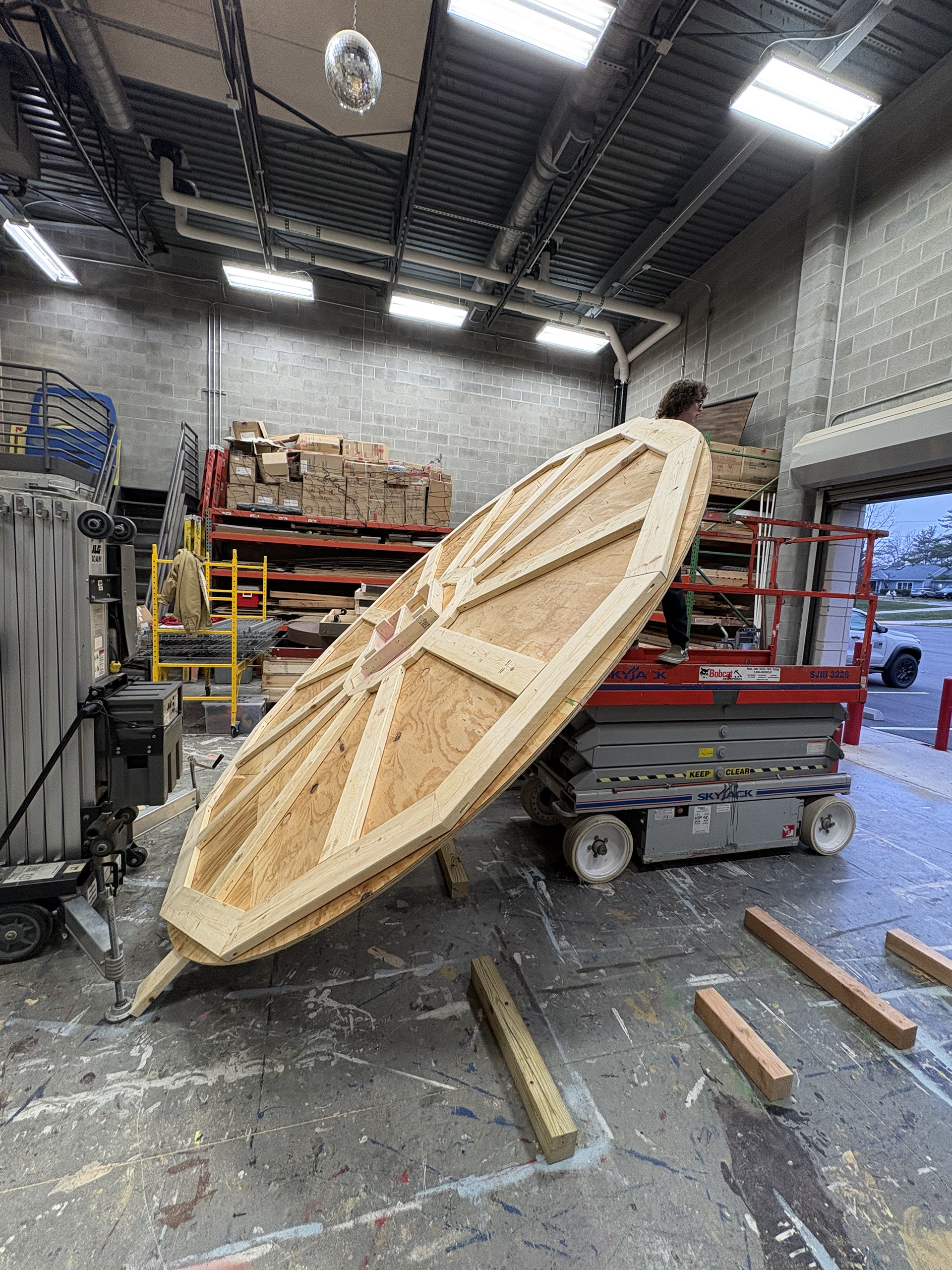
Flipping Structure for Wheel Installation
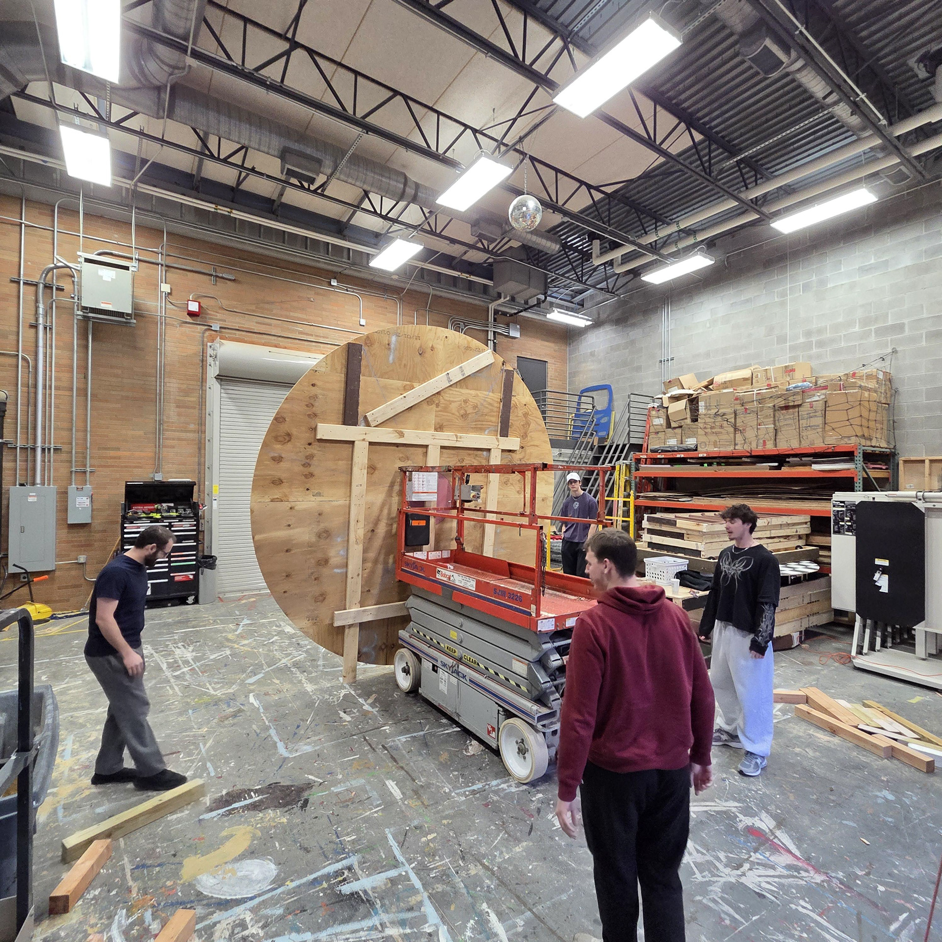
Flipping Structure for Wheel Installation
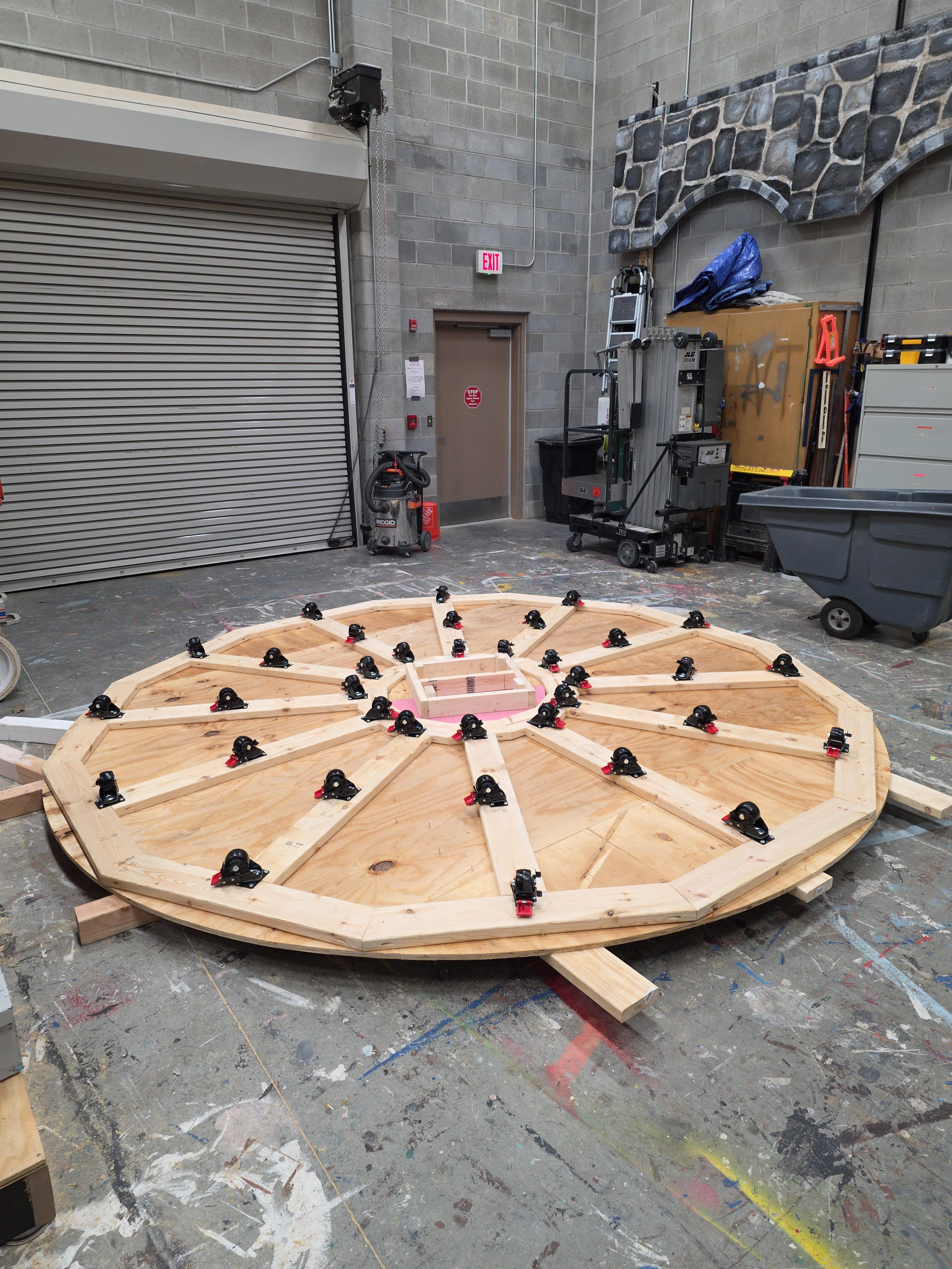
Caster Wheels Installed
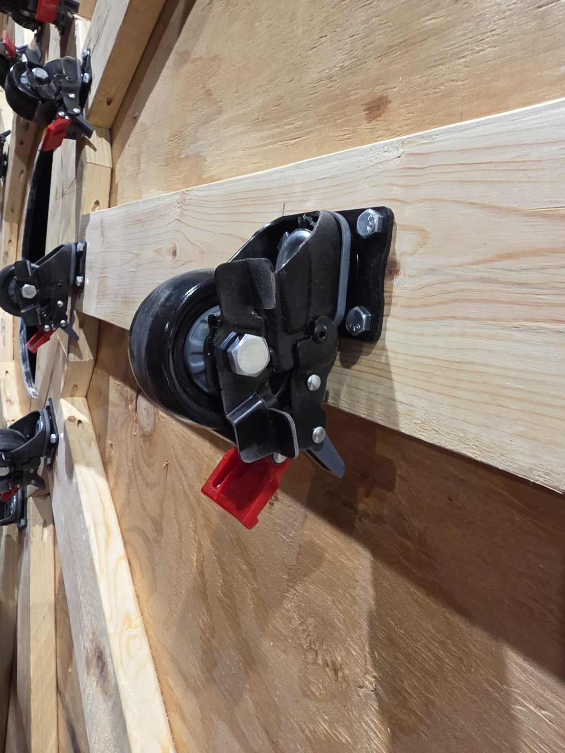
Close-up of Casters
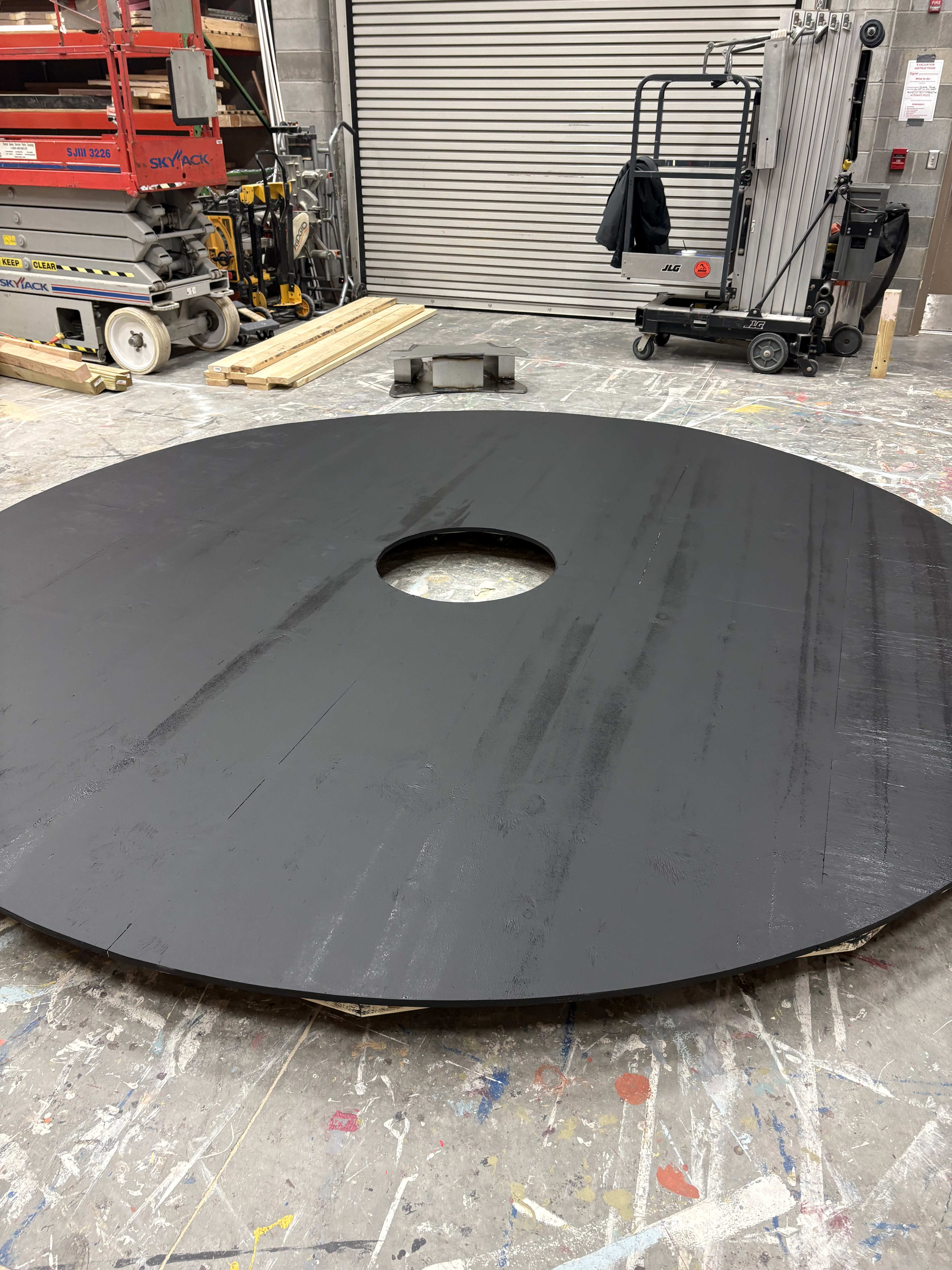
Structure Surface Prepped and Painted
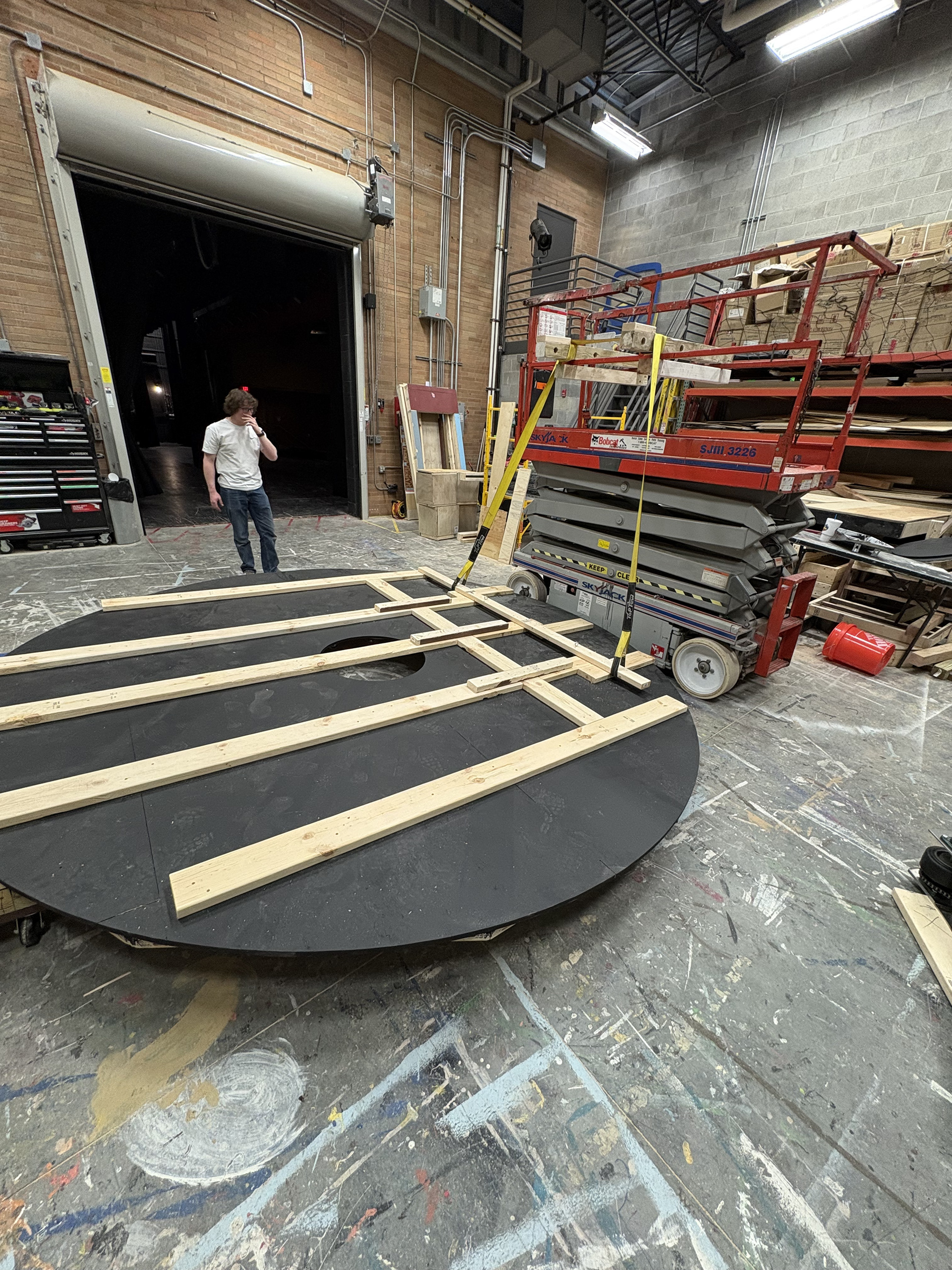
Structure Framed and Ready for Load-in
Traction Drive System Reference Project on GitHub

First Part Sourced - Drive Motor

BOM Did Not Specify Double-Shaft Gear Reducer for Two Sprockets
Wiring Diagram Did Not Account for Use of Alternative Drive Motors
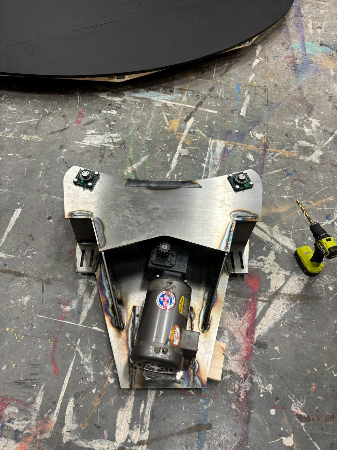
Motor Mount Required Modification to Motor Base for Compatibility
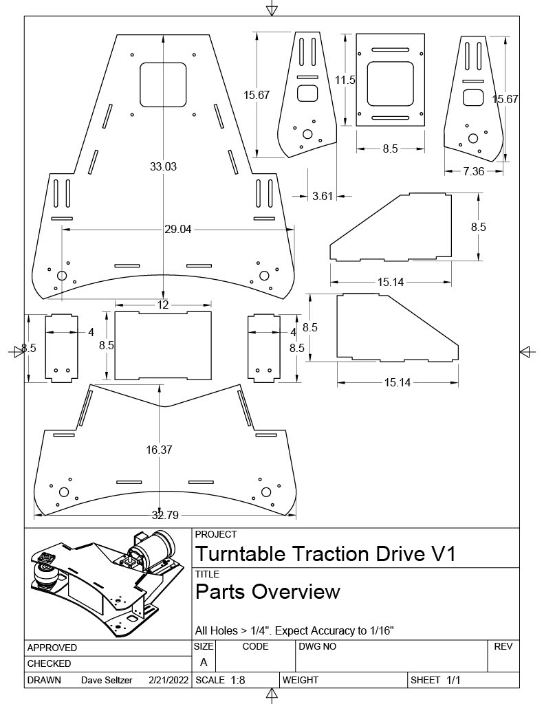
Custom Steel Part Drawings
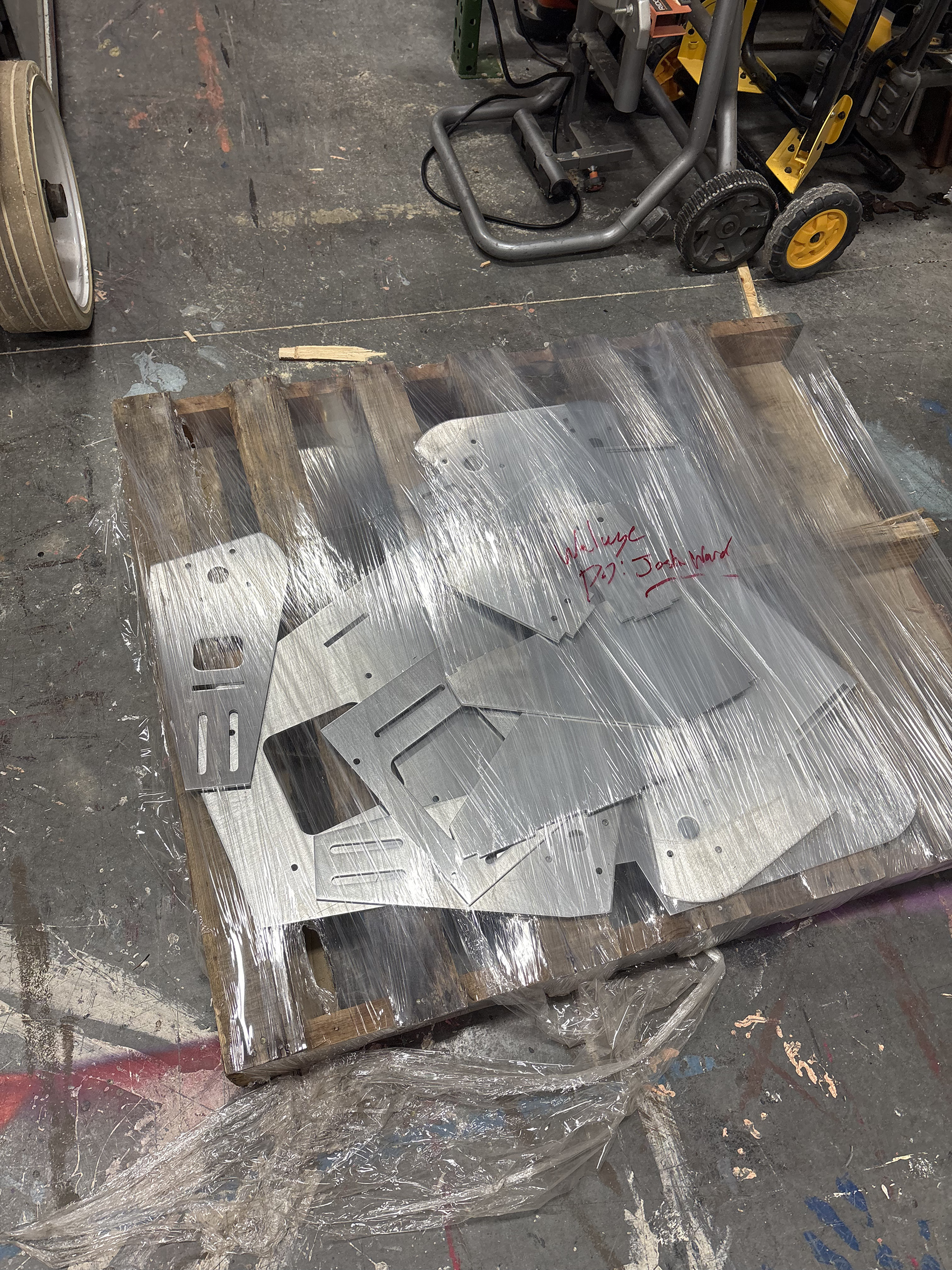
Custom Steel Parts Delivered
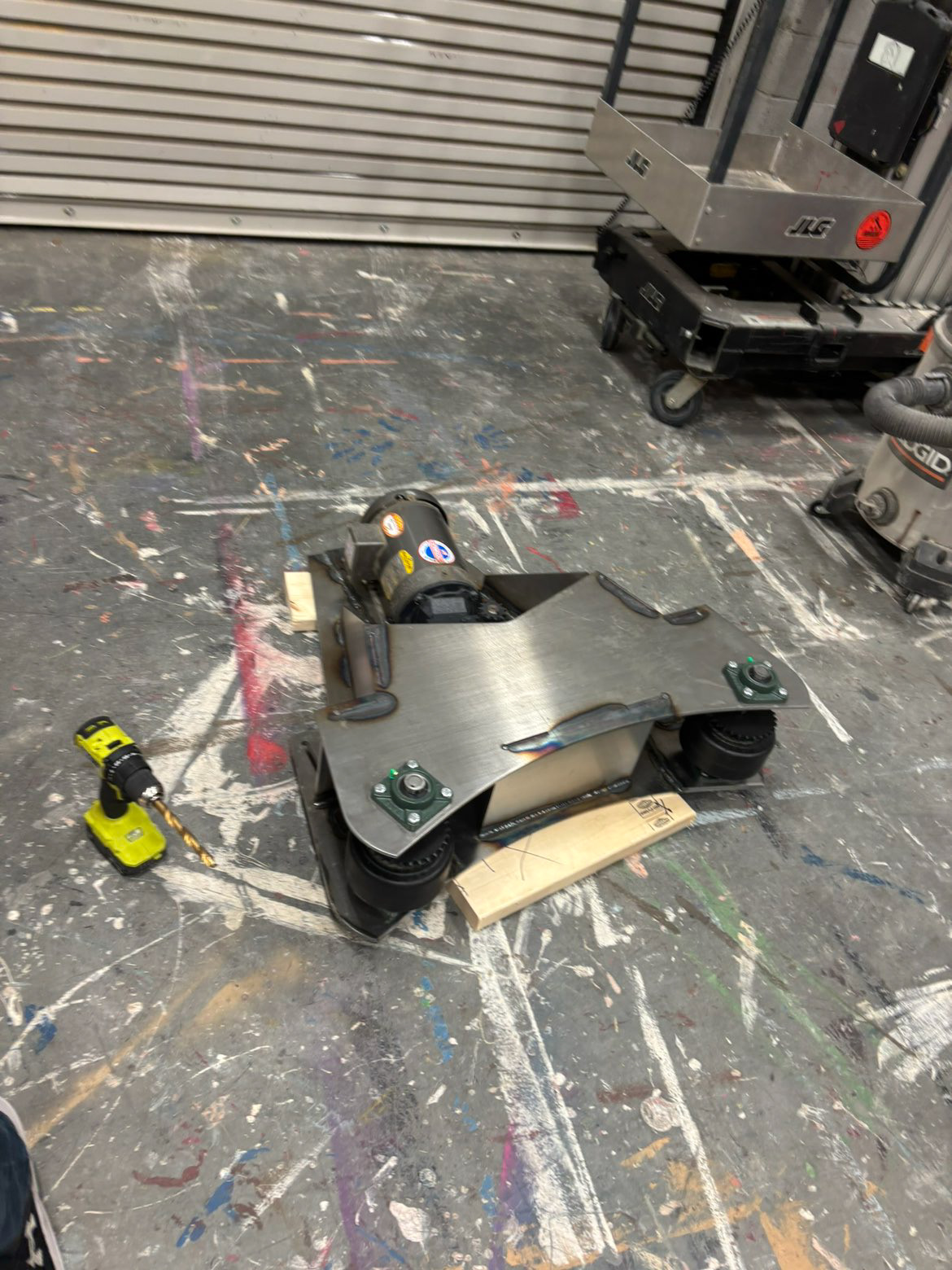
Drive System Assembled
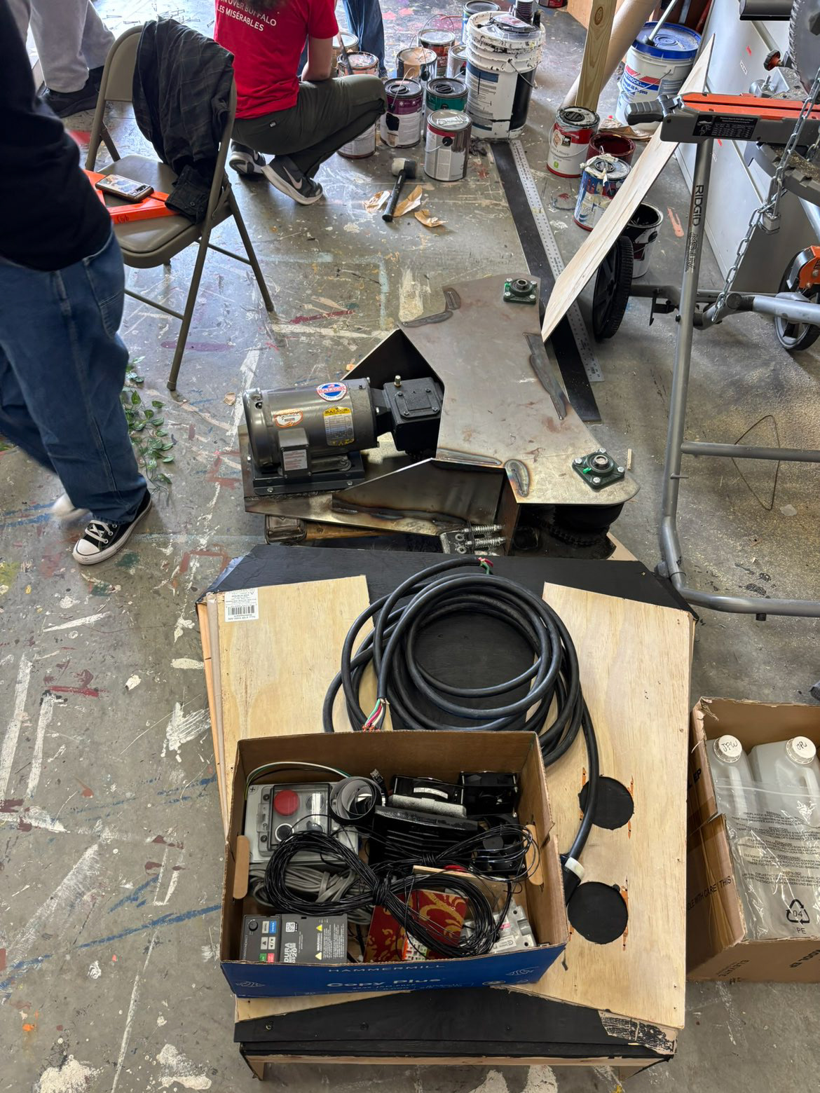
Preparing for Integration with Revolve Structure
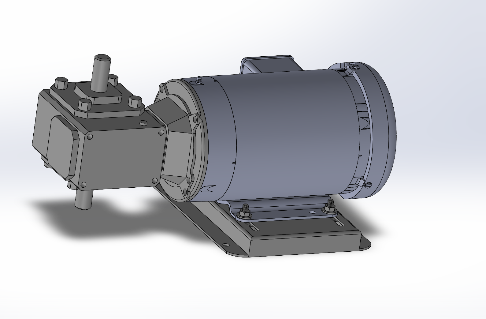
Reviewing CAD Part Files Revealed the Intent for a Double-shaft Gear Reducer to be Used
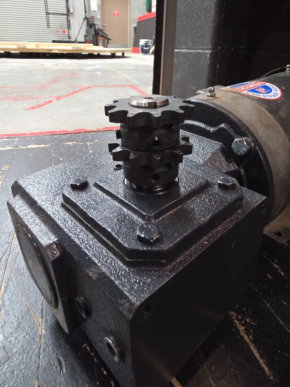
Stacked Sprockets on Our Gear Reducer
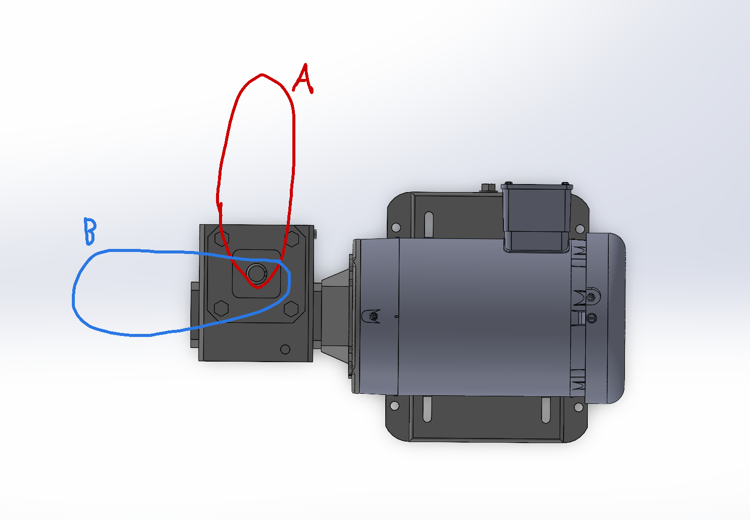
Exploring Drive Chain Path Options
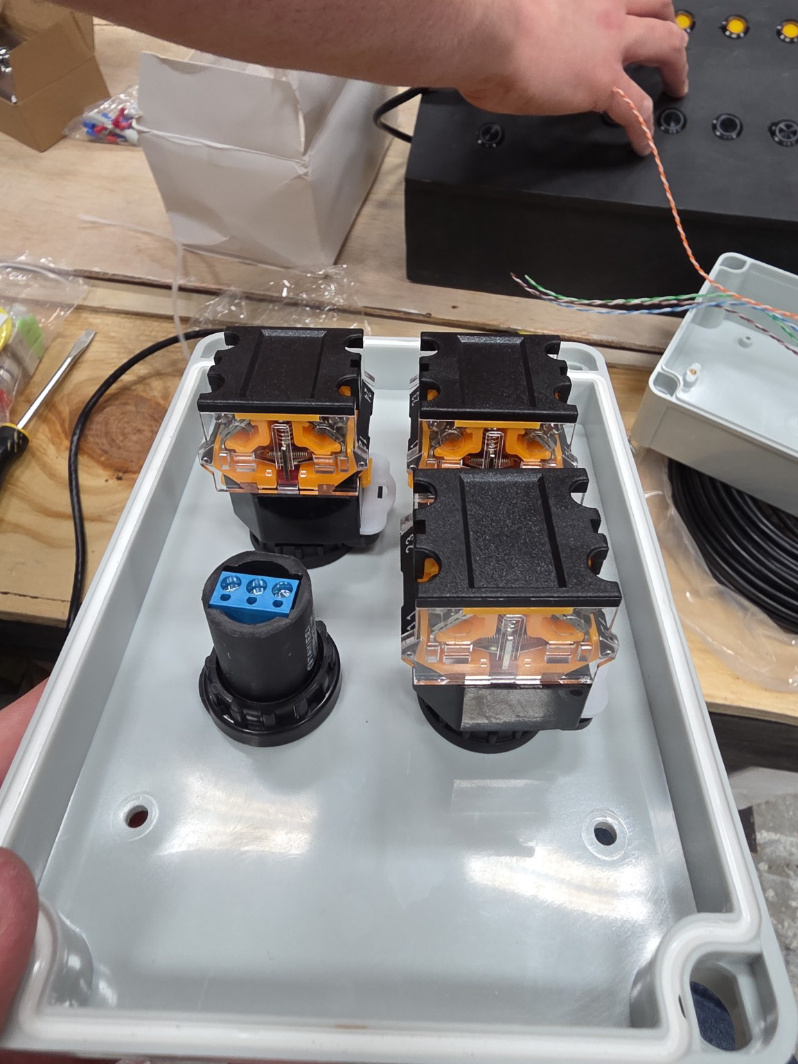
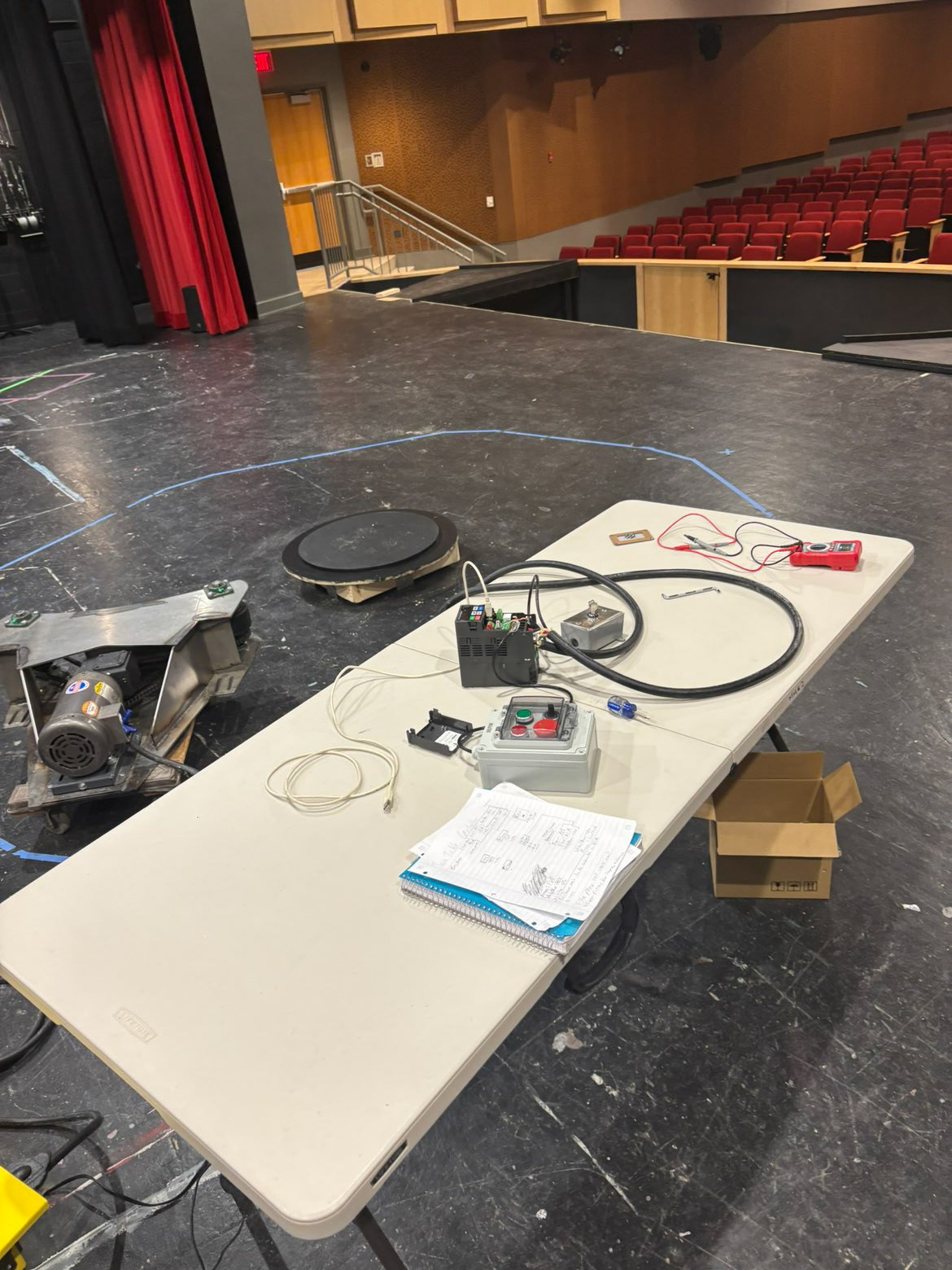
Assembling the Controller

Initial Controller
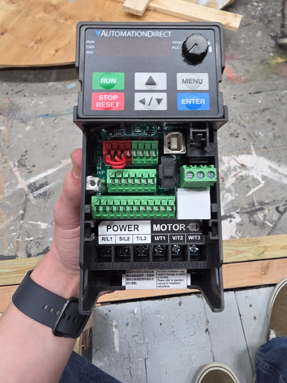
VFD
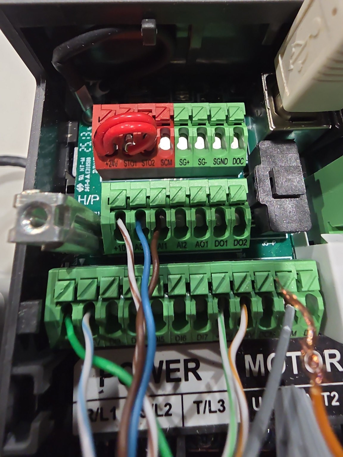
Controller Wired to VFD
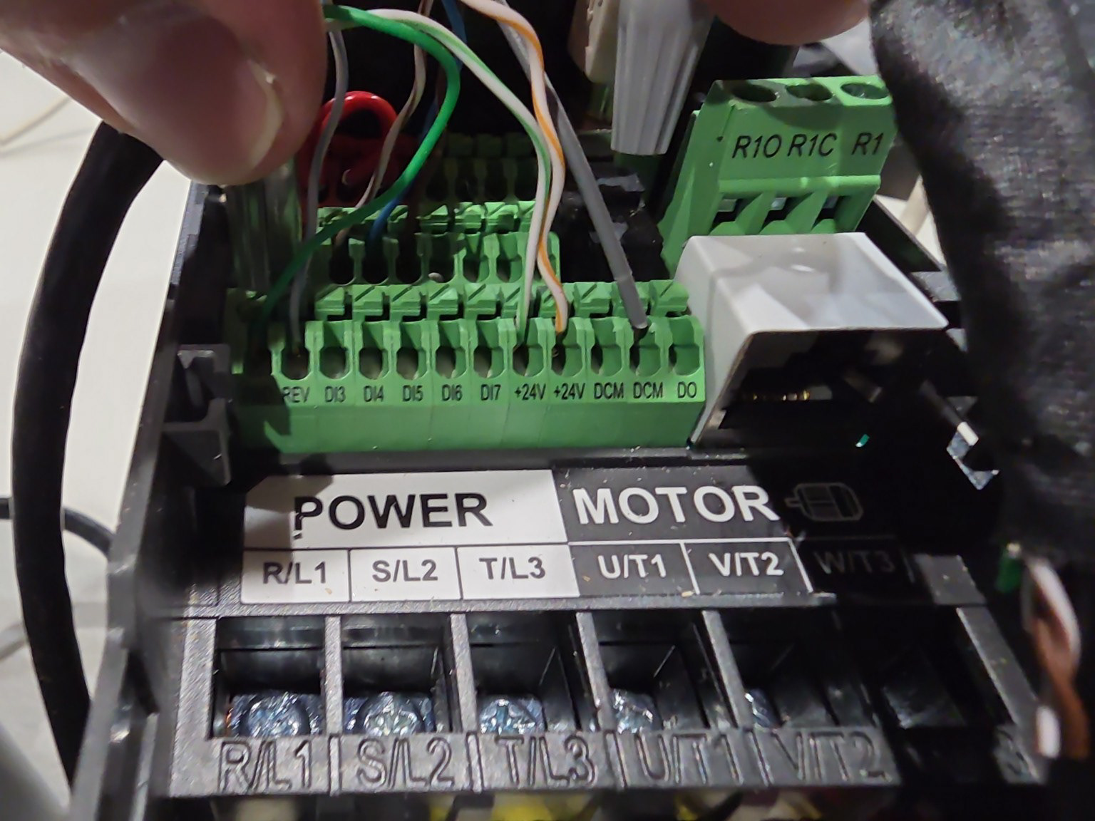
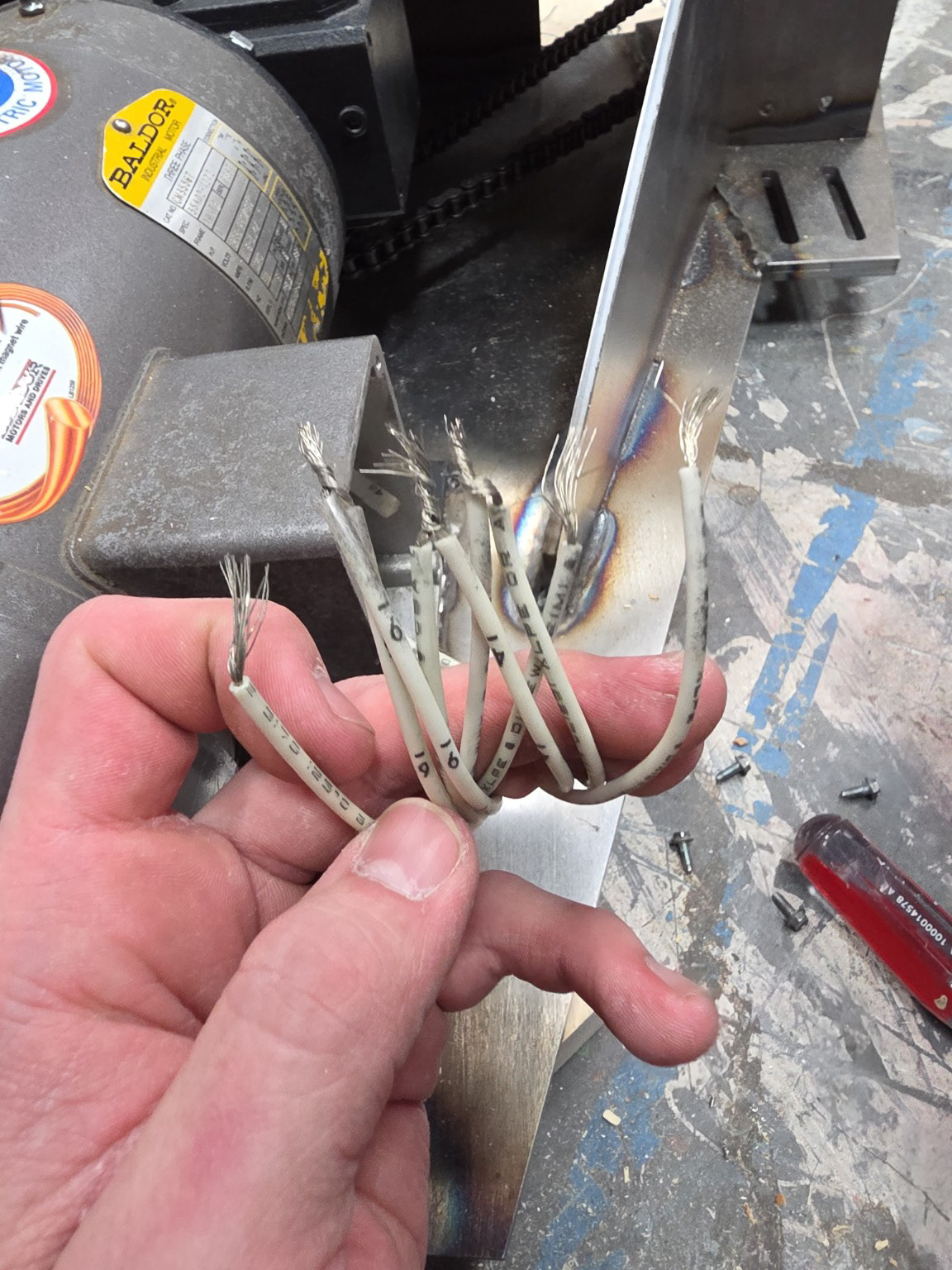
Ensuring Proper Wire Termination
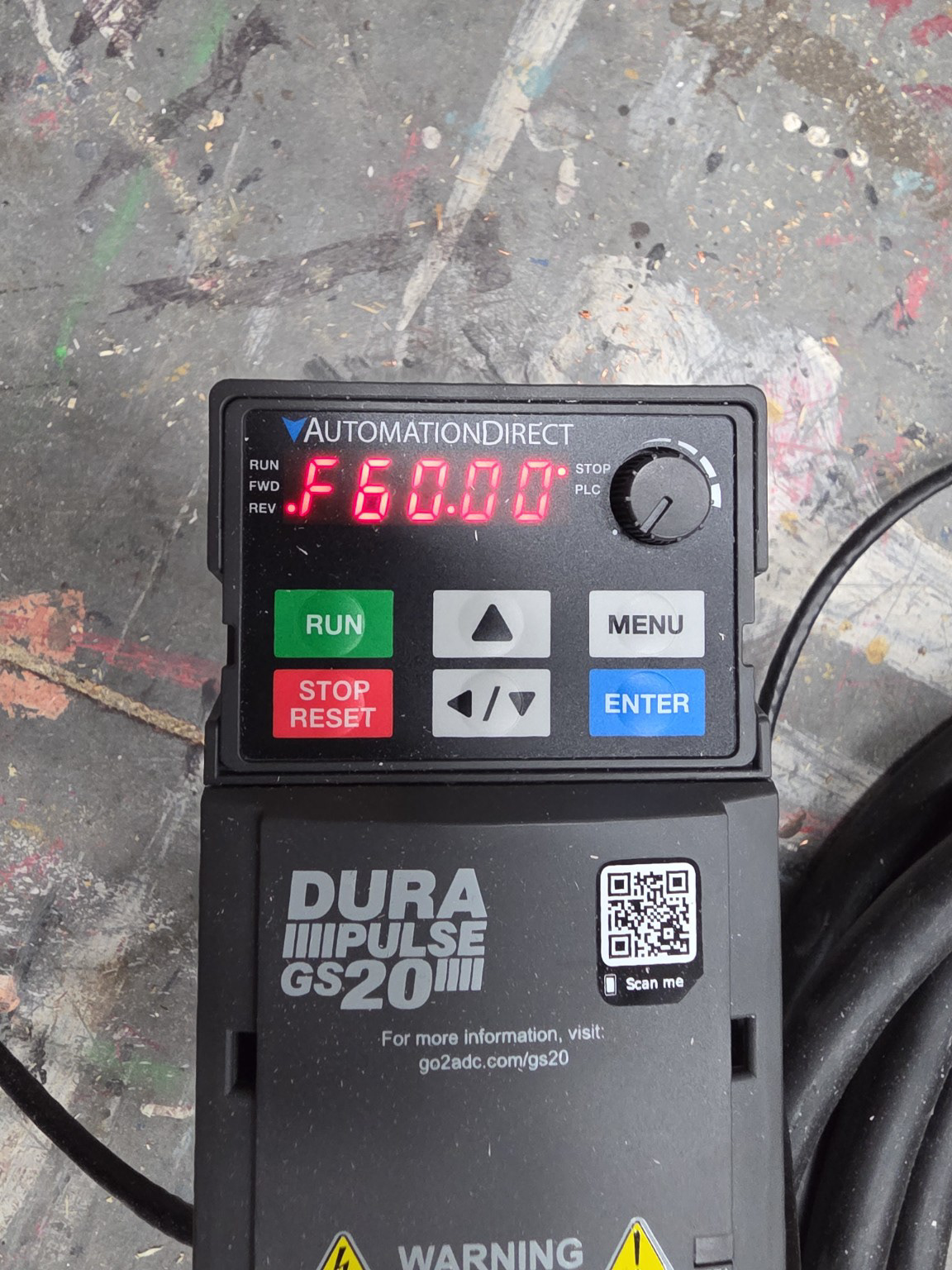
VFD Powered
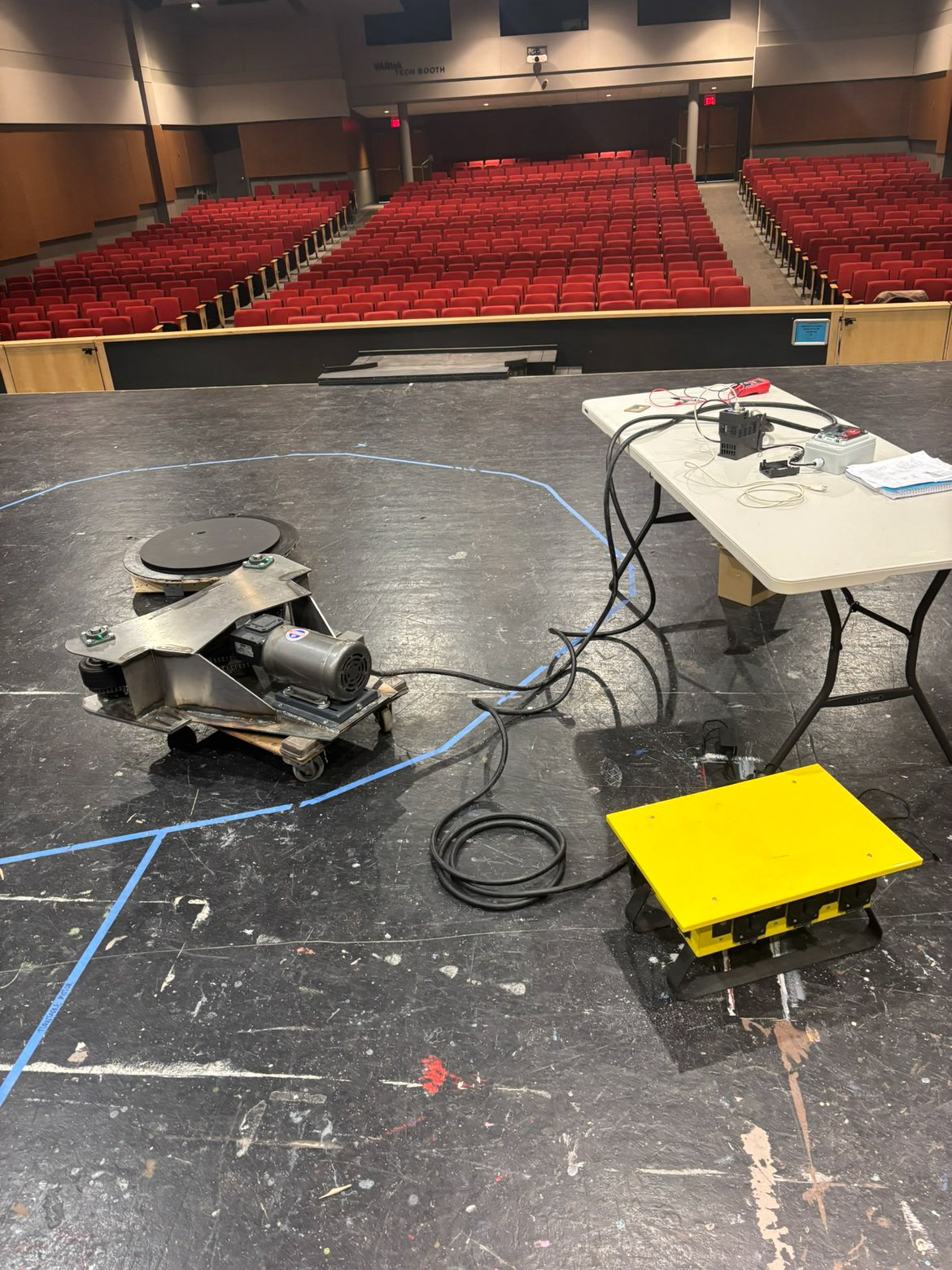
Initial Testing Setup
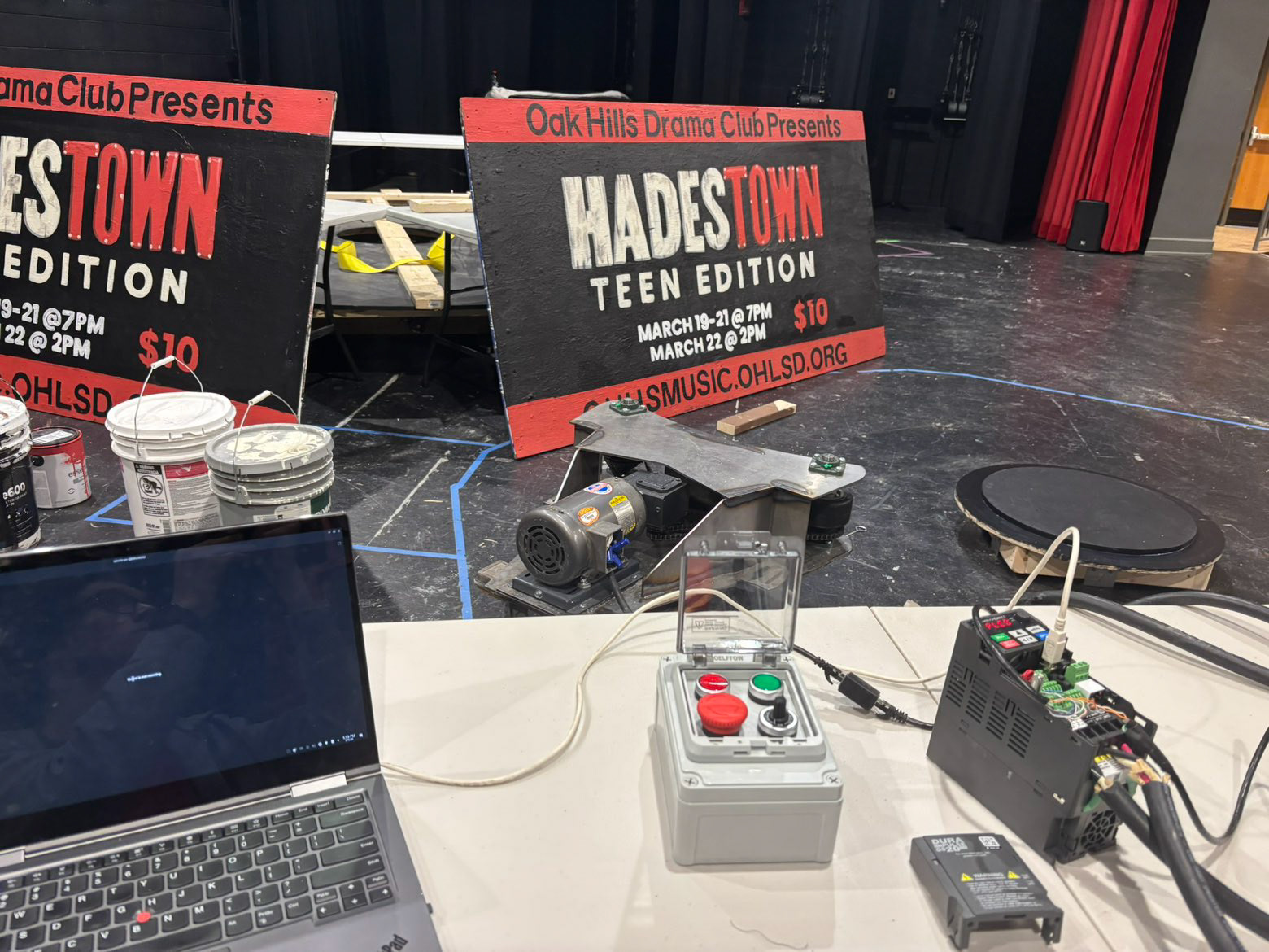
Programming VFD to Remote Control
Swapping Buttons for Selector Switches
Integrating Keyed E-stop
Revolve Structure Loaded
Initial VFD programming, which revealed that our momentary start and stop buttons were not the correct hardware for the control process we wanted.
Momentary buttons were swapped for selector switches, which allowed for open and closed circuits to trigger run/off modes as well as forward/reverse direction control.
Initial Grip-tape Traction Material
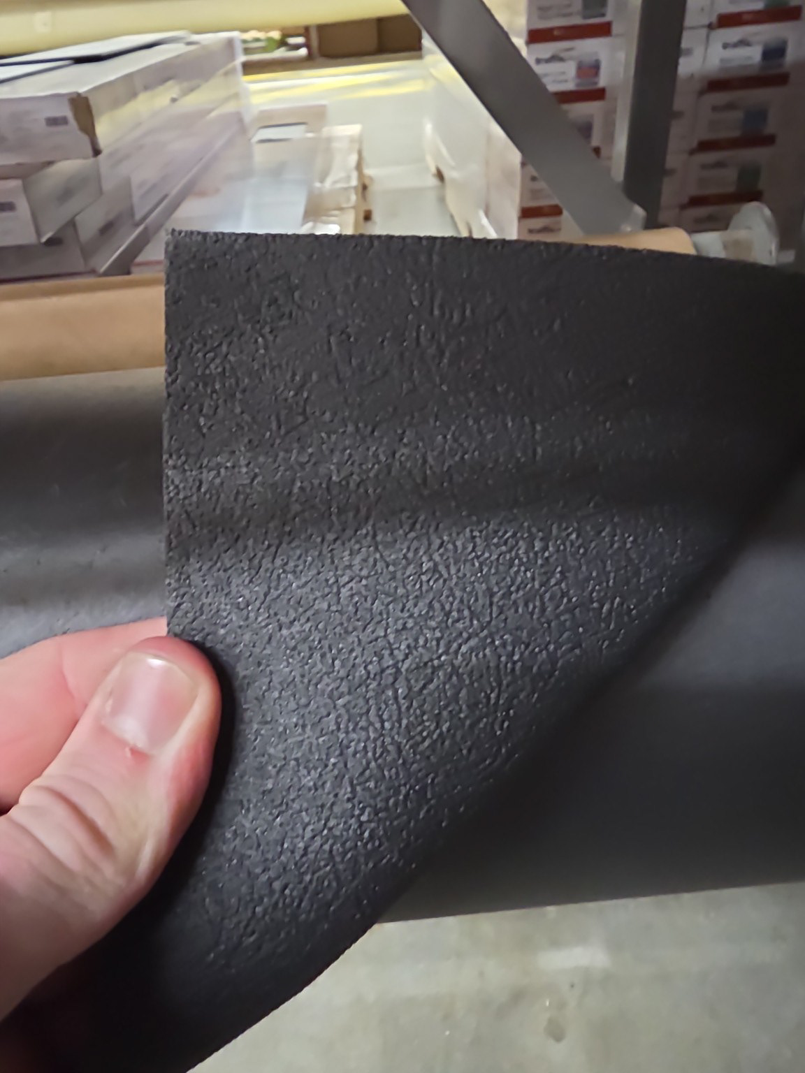
Rubber Material Used After Failure of Grip-tape
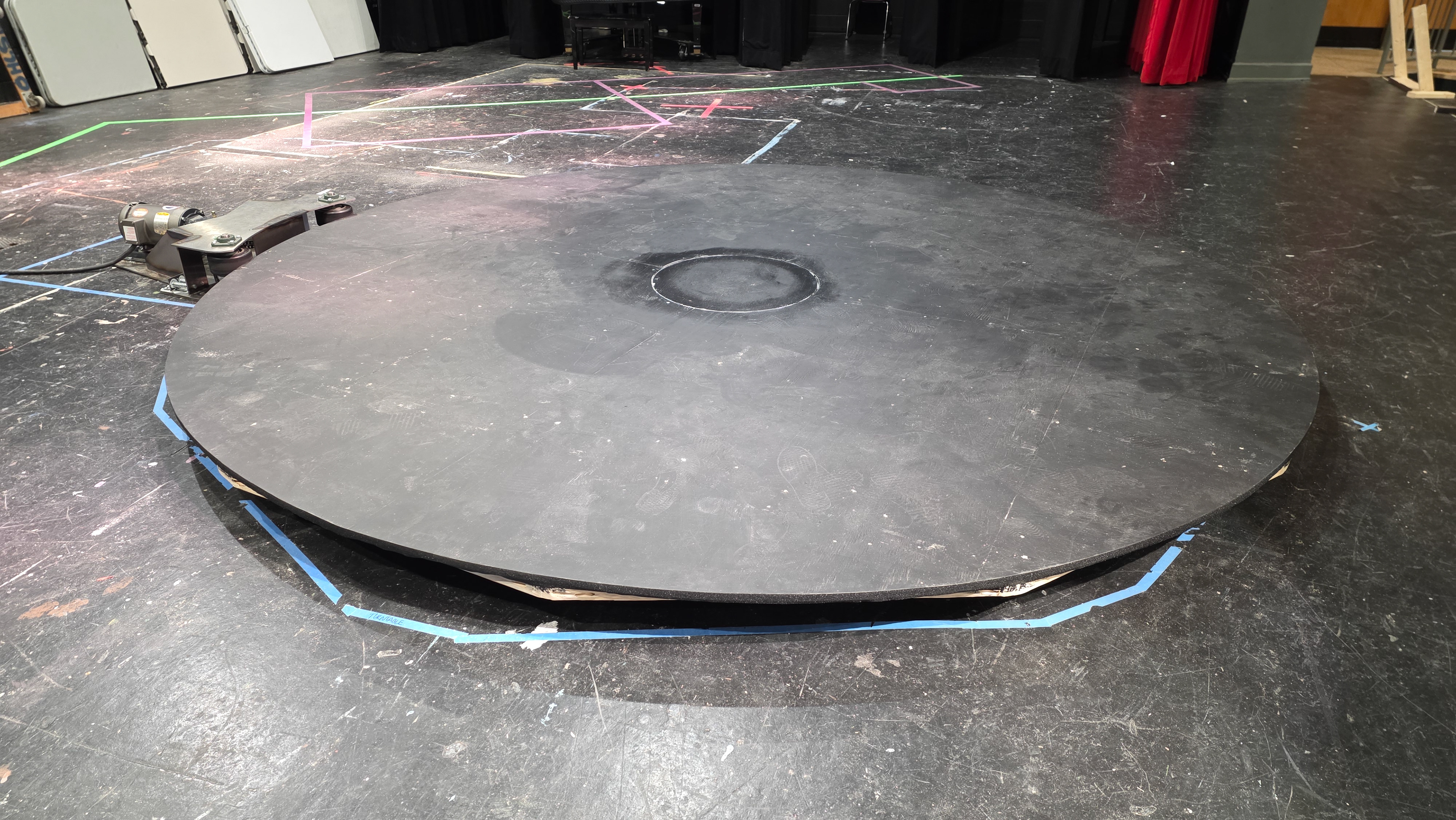
Revolve System Fully Loaded and Operational
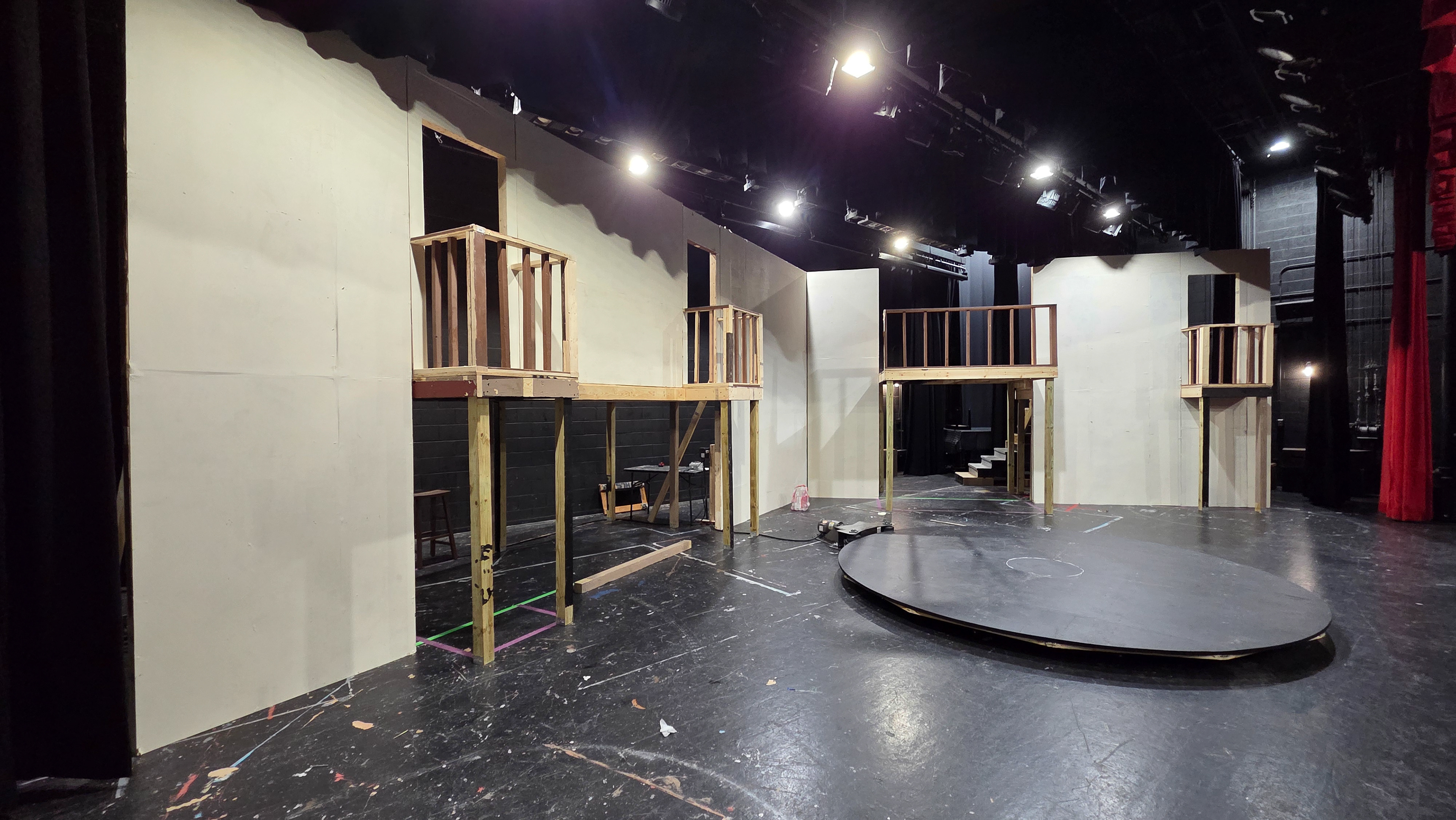
Additional Set Load-in Progress
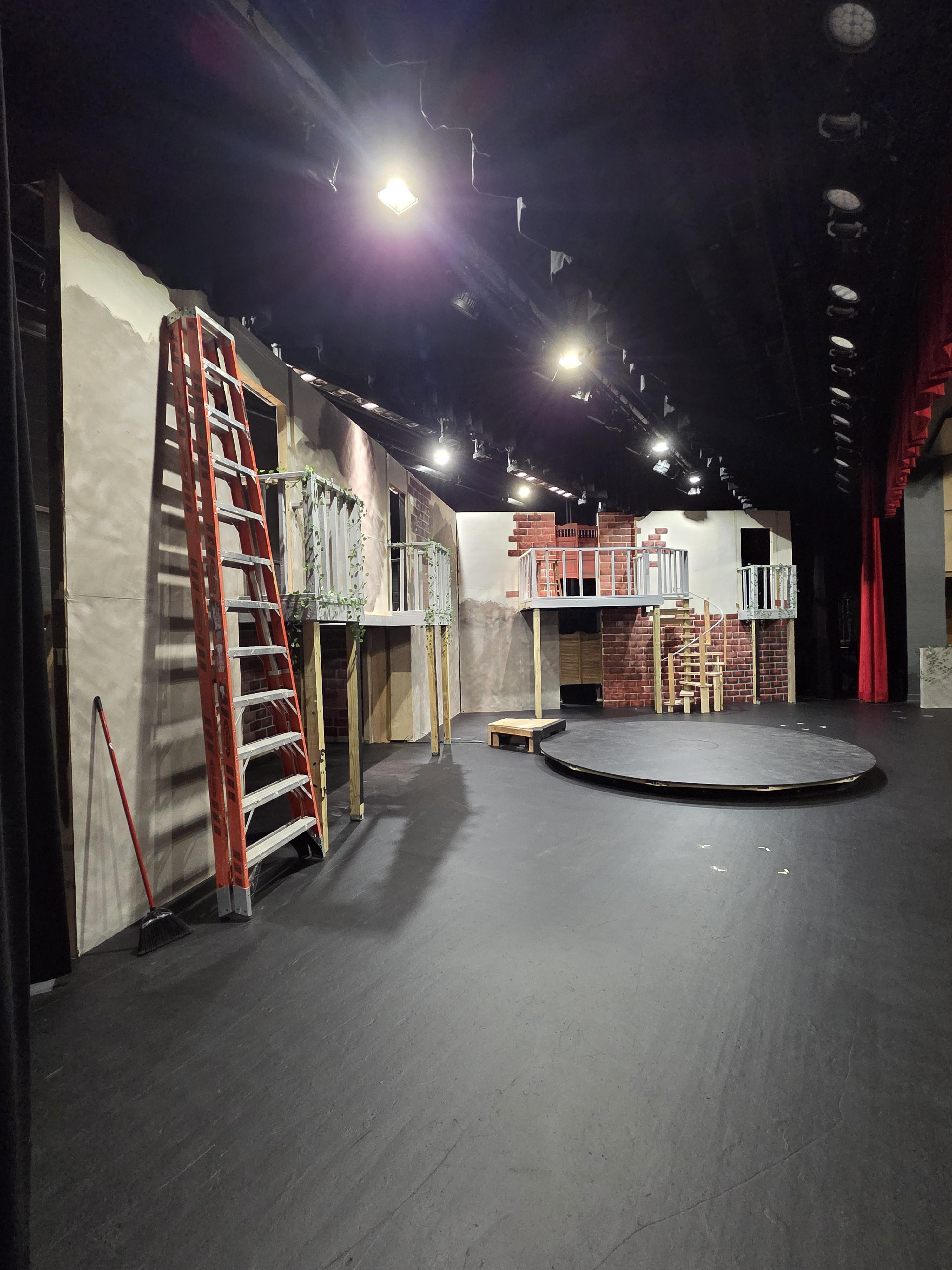
Floor Surfaces Freshly Painted and Initial Integration of the Outer Shell
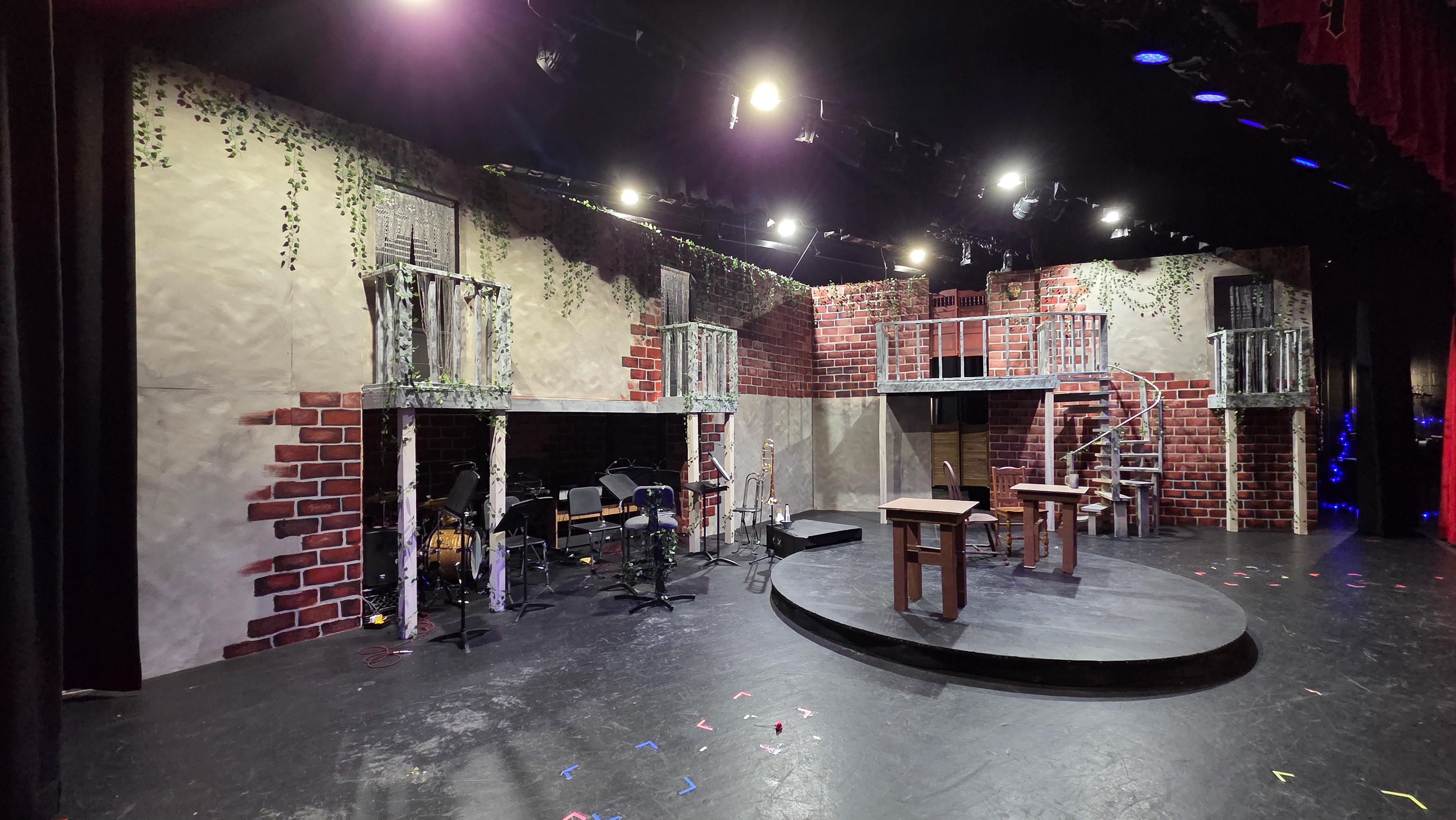
Set Load-in Completed
Cooling System Preparation
Cooling System Preparation
Mounting the Stage Right Camera
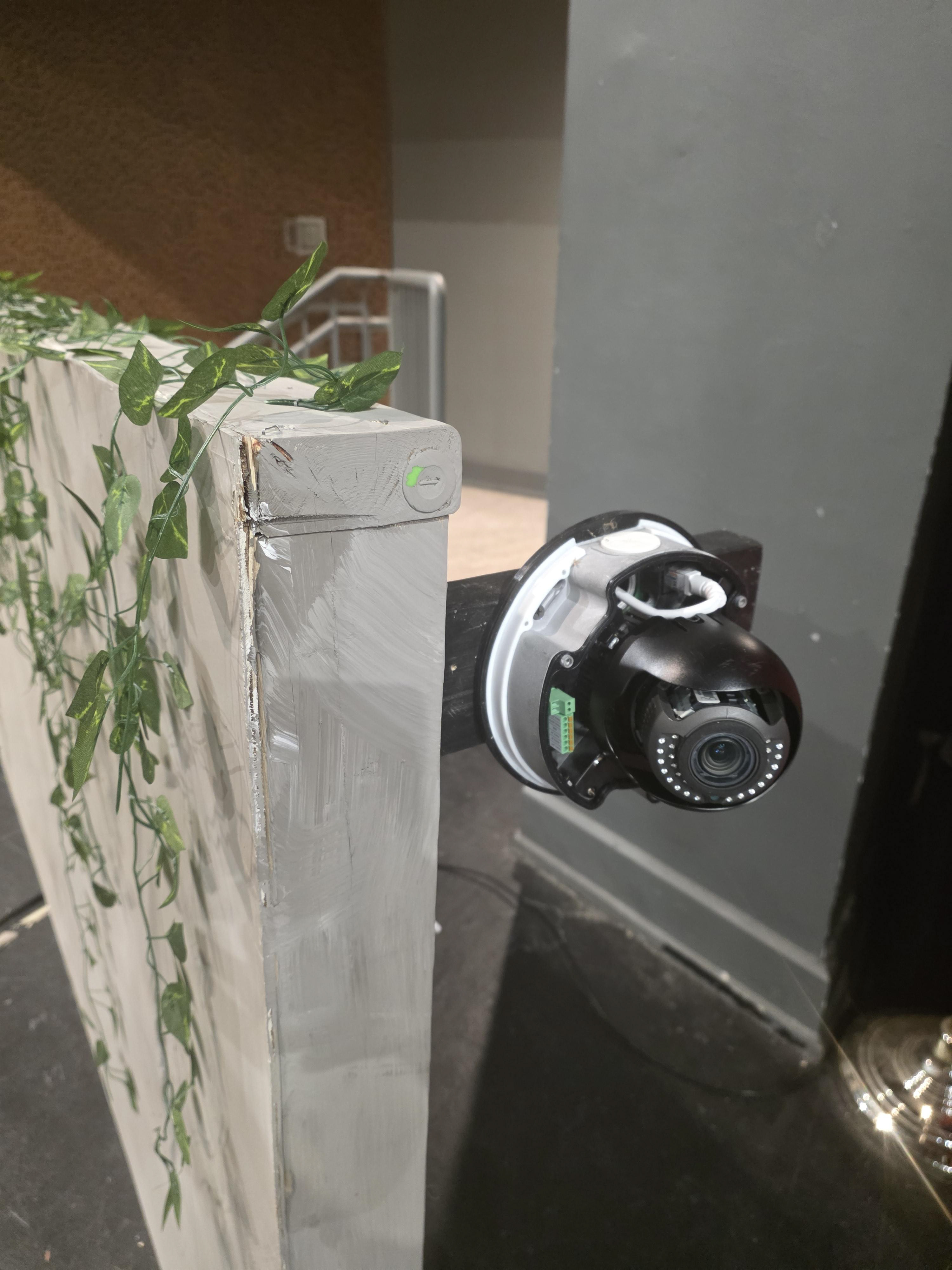
Mounted Stage Right Camera
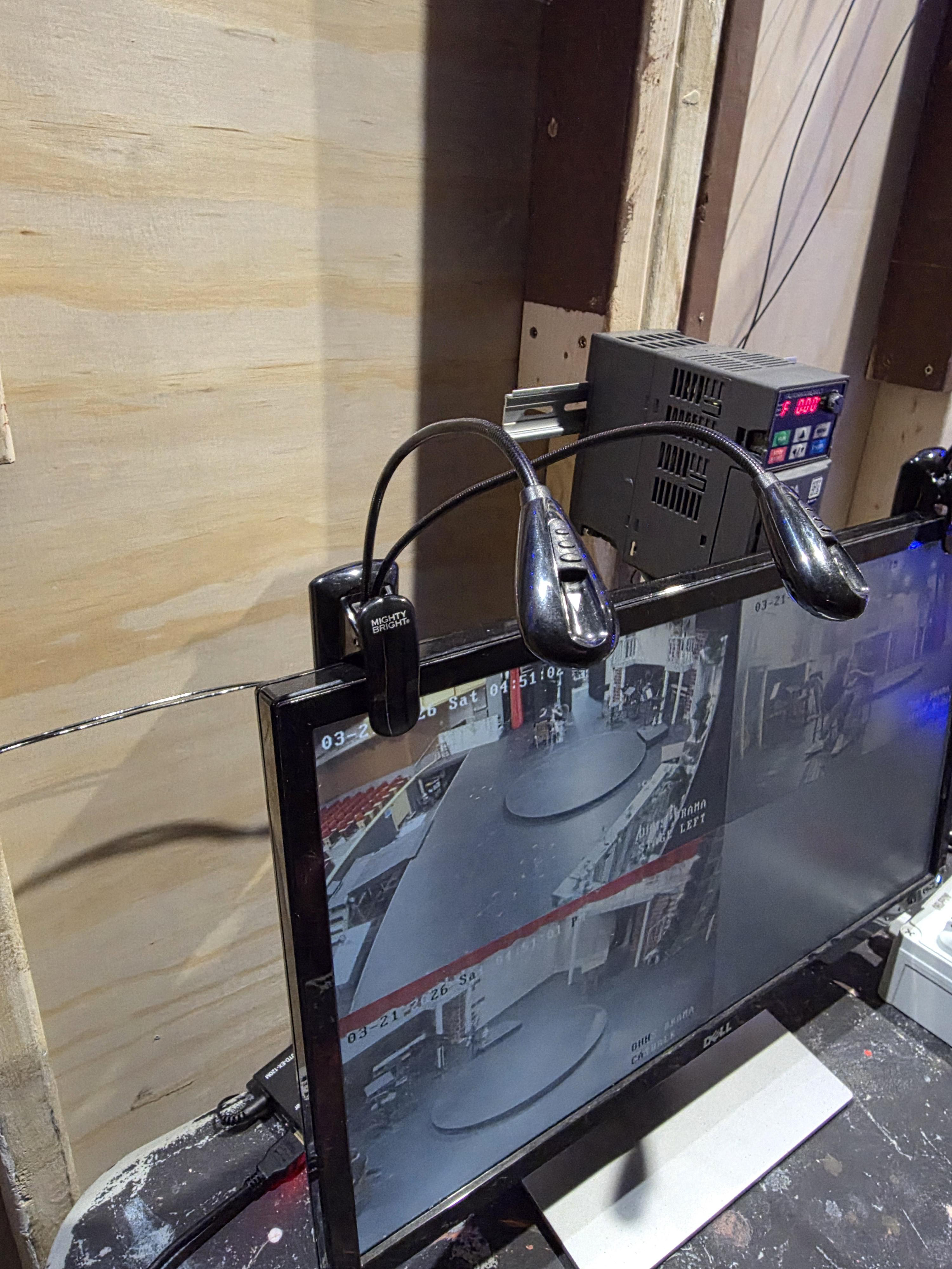
First Views of Live Feed from Turntable Operator's Desk
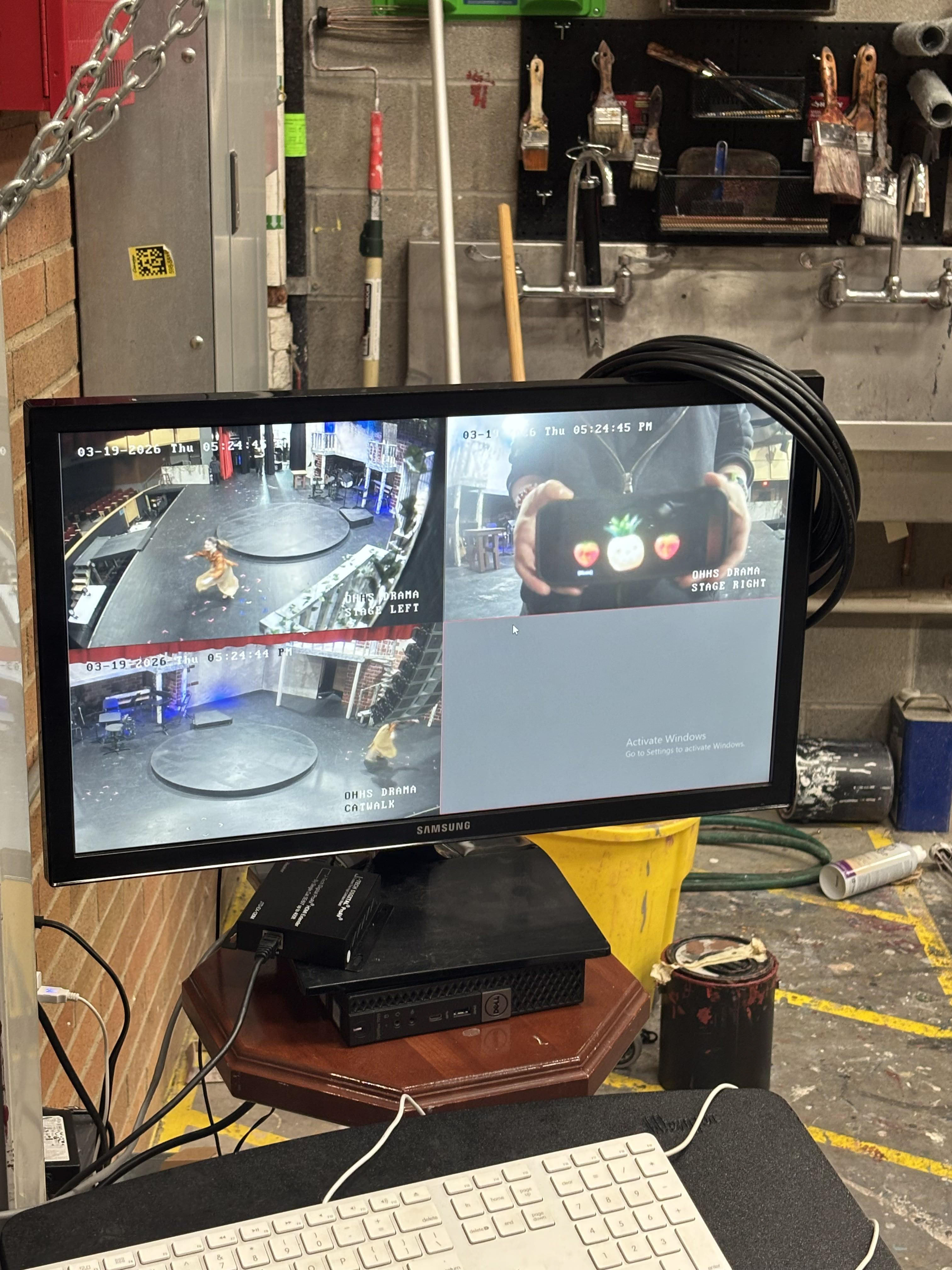
Added Monitor for Stage Manager
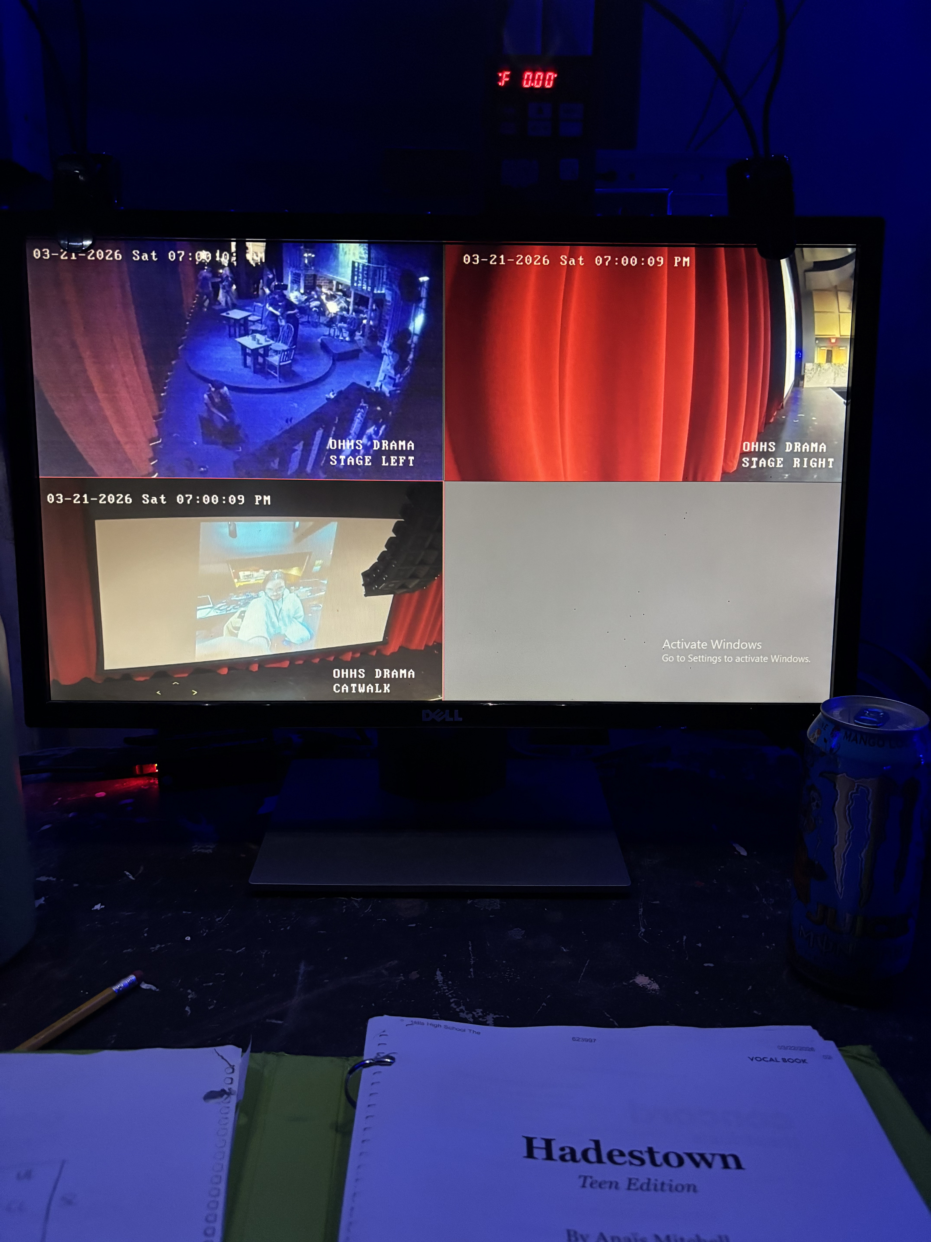
Feed in-use Pre-Performance
Technical Aspects of the Production are Fully Operational and Cleared for Performances
If It's True
Wait for Me Reprise
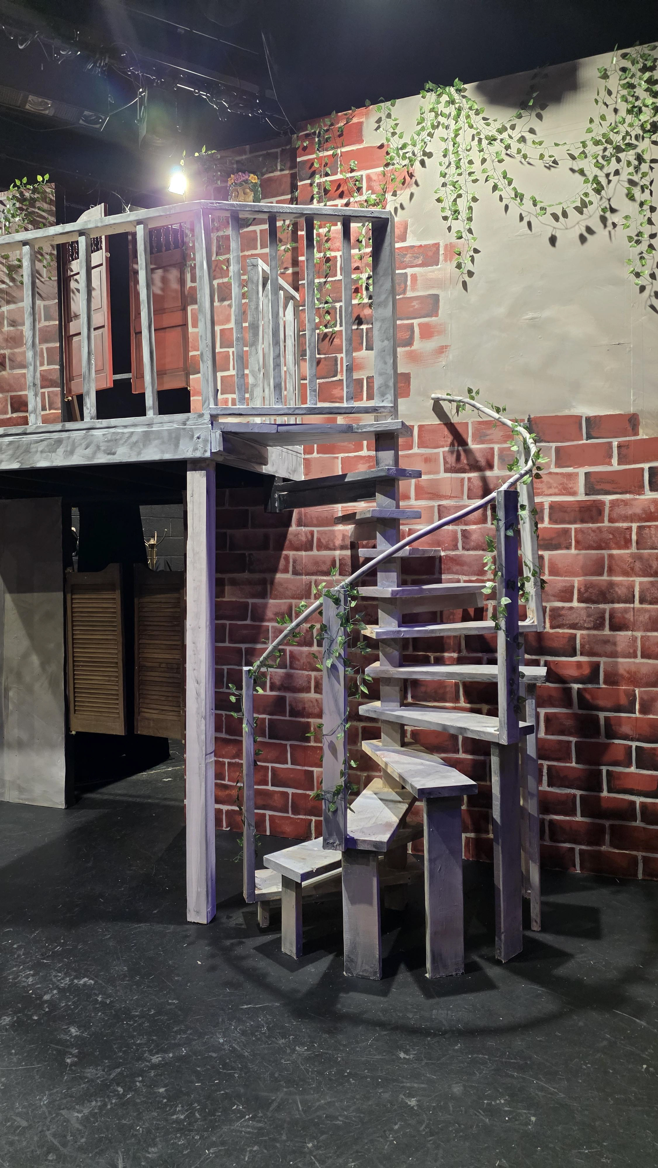
Spiral Staircase

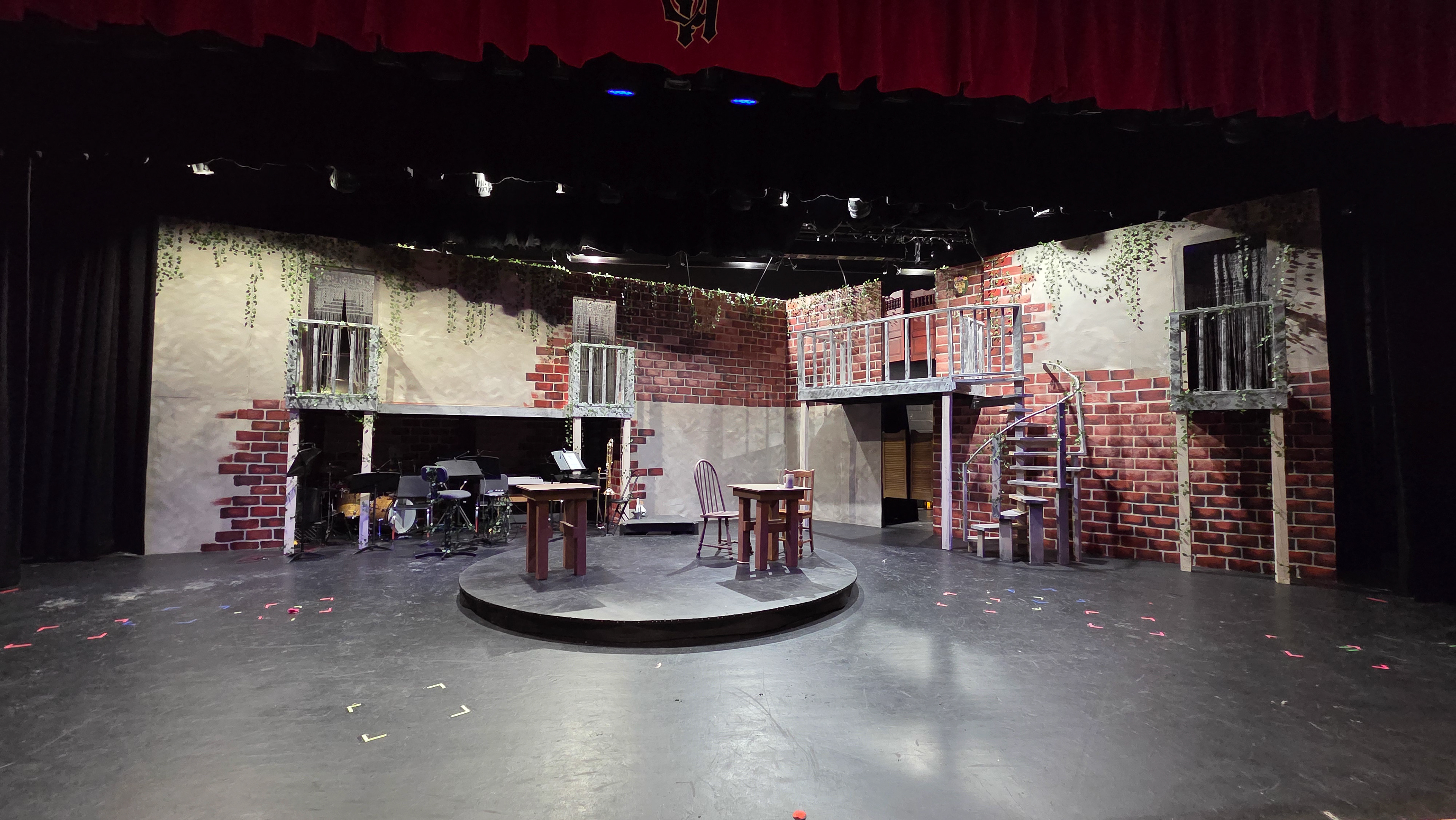
Fully Completed Set
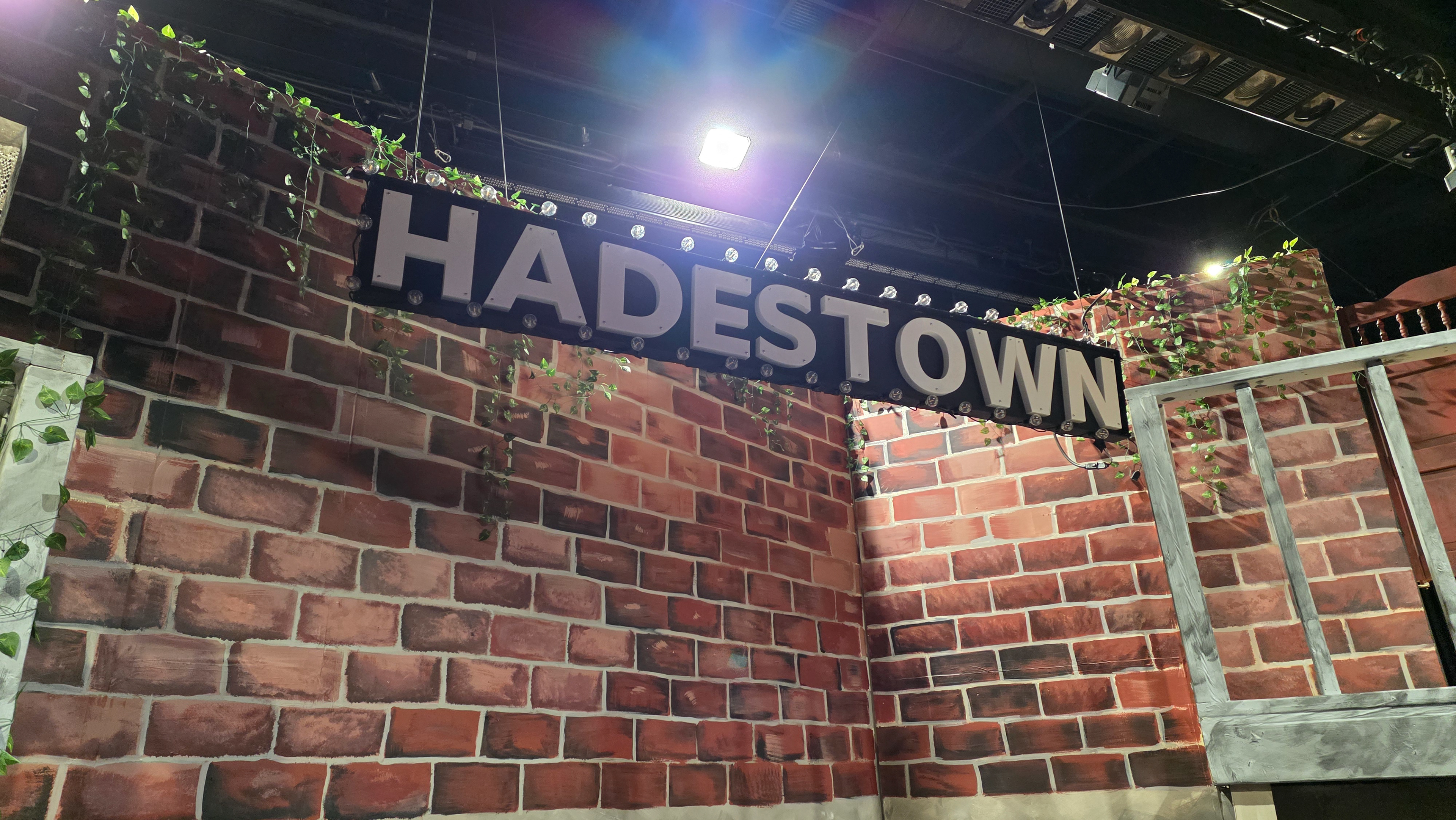
"HADESTOWN" Marquee Sign
Marquee Sign Dropping In (Wait for Me)
Lighting Effects (Chant Reprise)
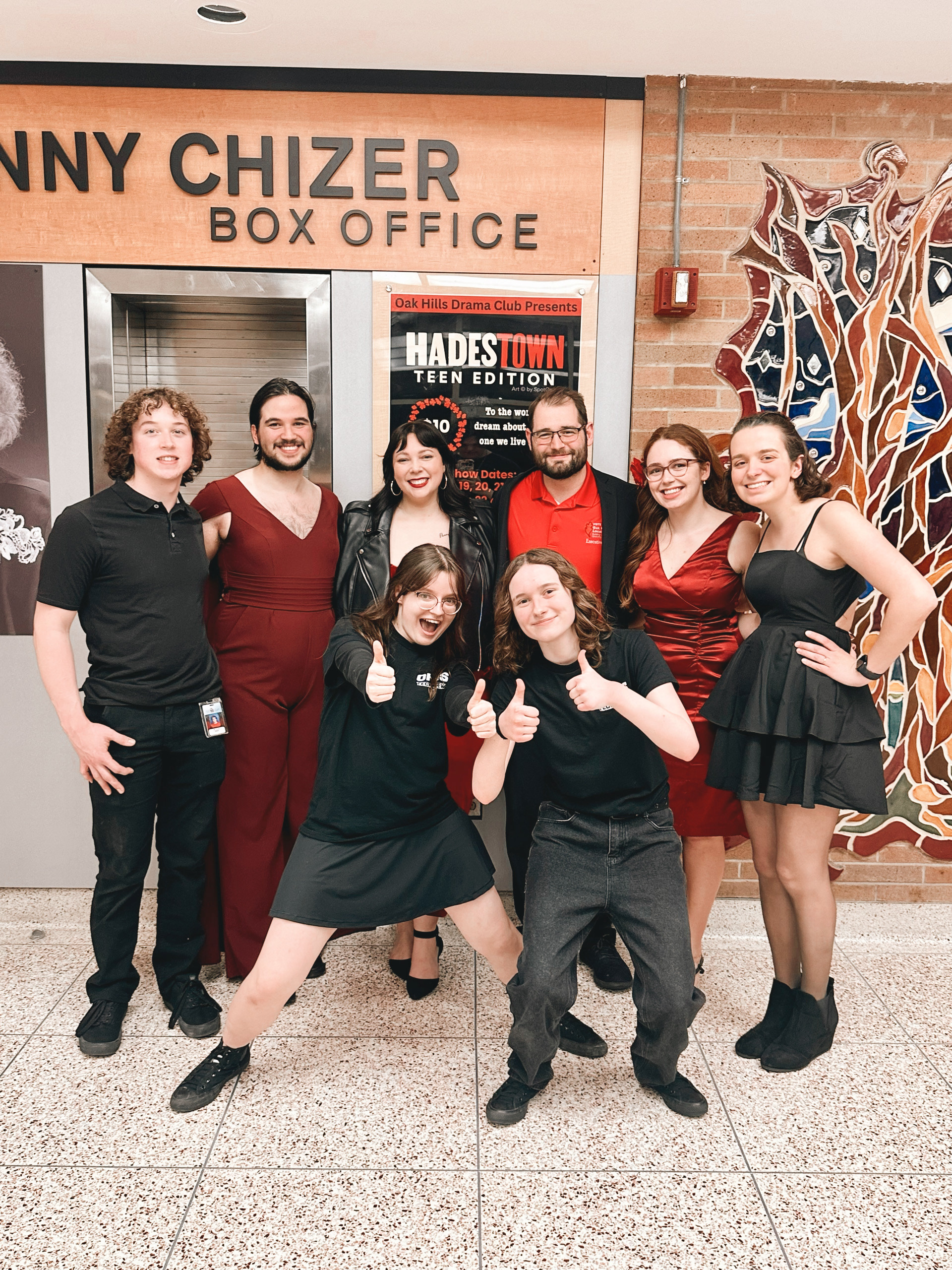
Pictured Left to Right: Corey Willett, Nick Rohr, Josie Wass, Ava Bredestege (front), Josh Ward, Jillian Hayden (front), Elena Radigan, Cassie Williams
Set Strike
Nolan Philips' Trombone Solo (Our Lady of the Underground)