Hadestown
Scenic Design · Technical Design · Fabrication · Automation
12-foot motorized stage revolve and scenic environment designed and built for a live production of Hadestown.
For this production, I developed a complete scenic environment centered around a custom 12-foot rotating platform with a stationary center. The project evolved from early hand sketches and spatial studies into a full-scale theatrical system combining scenic design, structural fabrication, mechanical systems, electrical controls, and live-show operation.
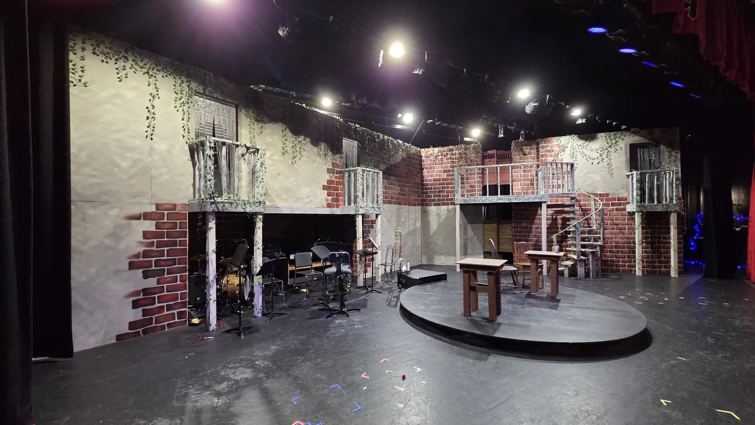
The finished set created a layered industrial world for the production while giving performers multiple elevations, entrances, balconies, and a continuously controllable rotating playing space.
FROM AN IDEA TO A SYSTEM
The challenge: Create a visually distinct interpretation of Hadestown that could support a large cast, multiple levels of choreography, and continuous scenic movement within the limitations of an existing school theater.
The design began with a simple floor-plan sketch. I knew early in the process that I wanted the stage to feel architectural rather than dependent on conventional movable scenery. The environment needed to provide multiple levels and pathways while keeping the center of the stage open enough to function as the production's primary playing space.
The earliest concept divided the architecture into two angled scenic walls surrounding a central circular platform. From there, I began testing scale, sightlines, entrances, balcony positions, stairs, and circulation in 3D.
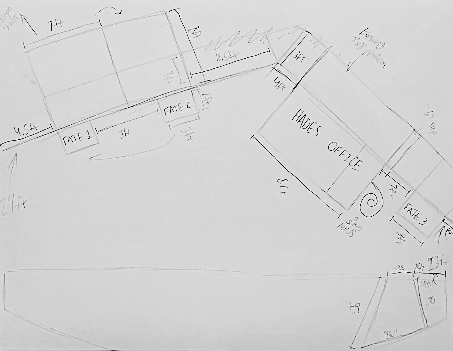
Initial Rough Sketch
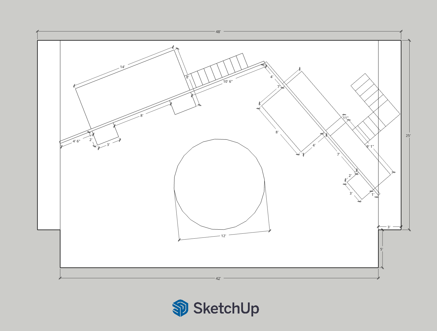
Finished Floor Plan
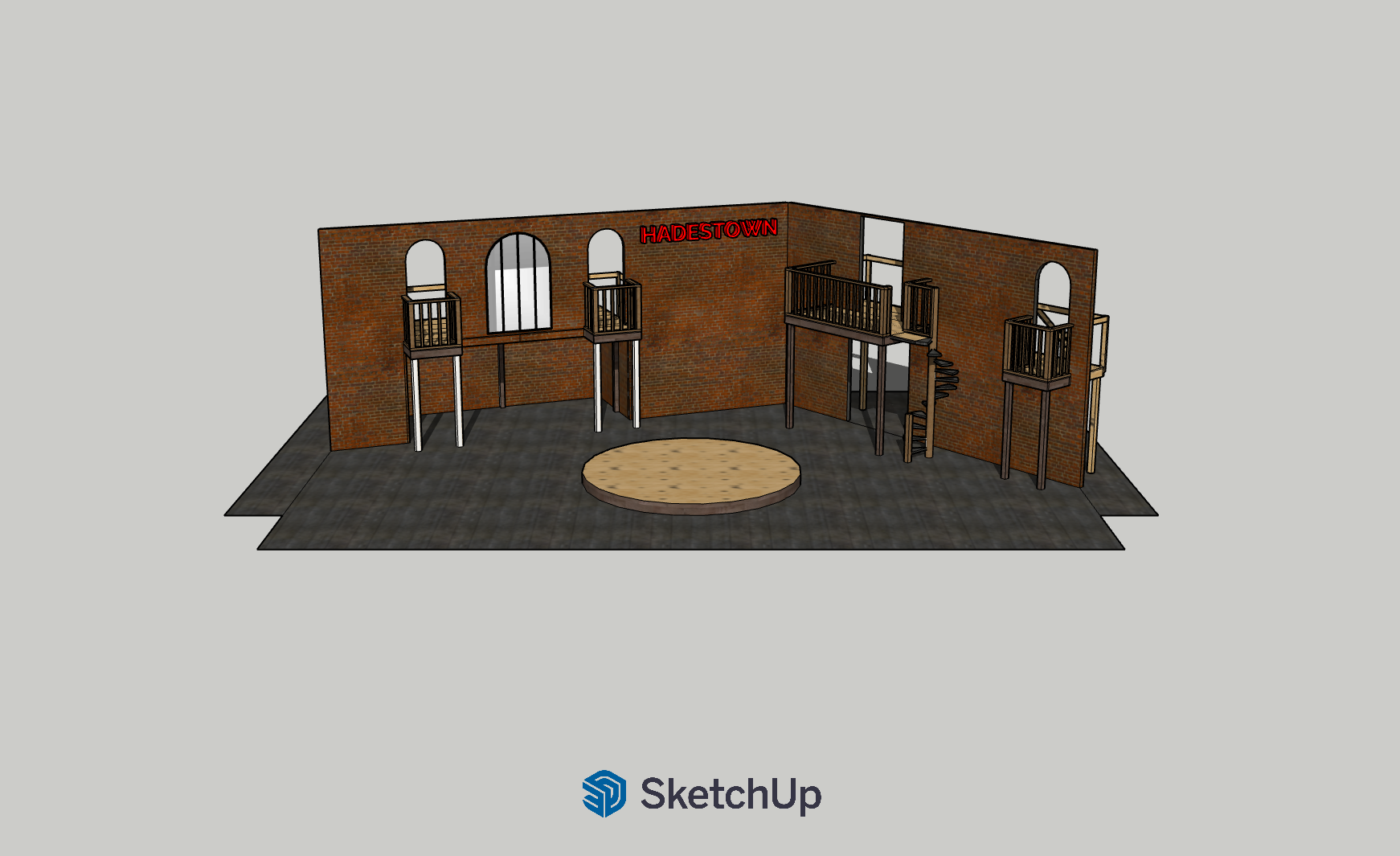
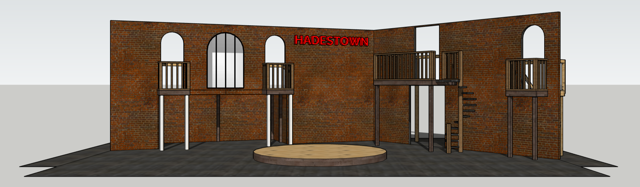
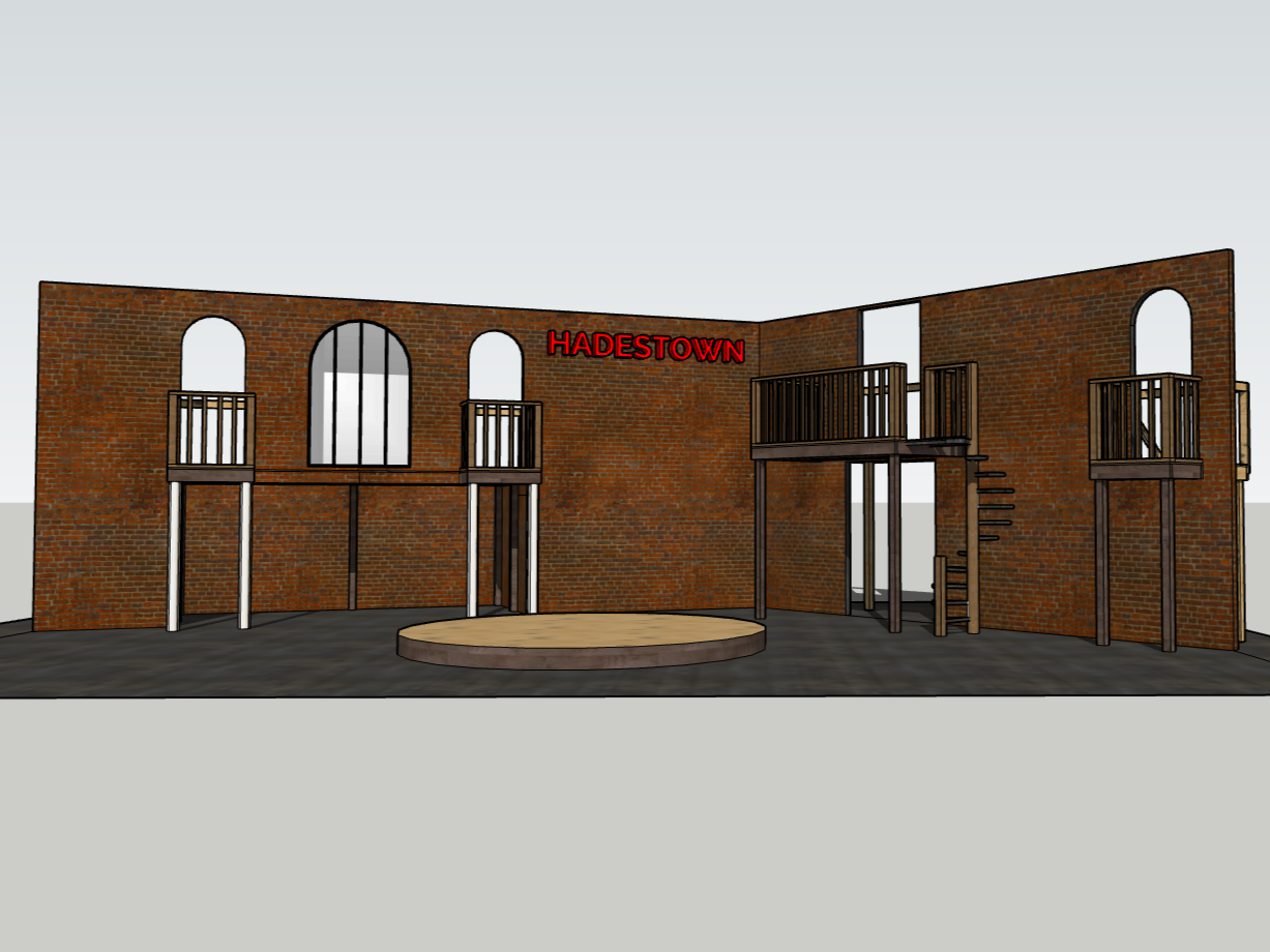
Finished 3D Model Front
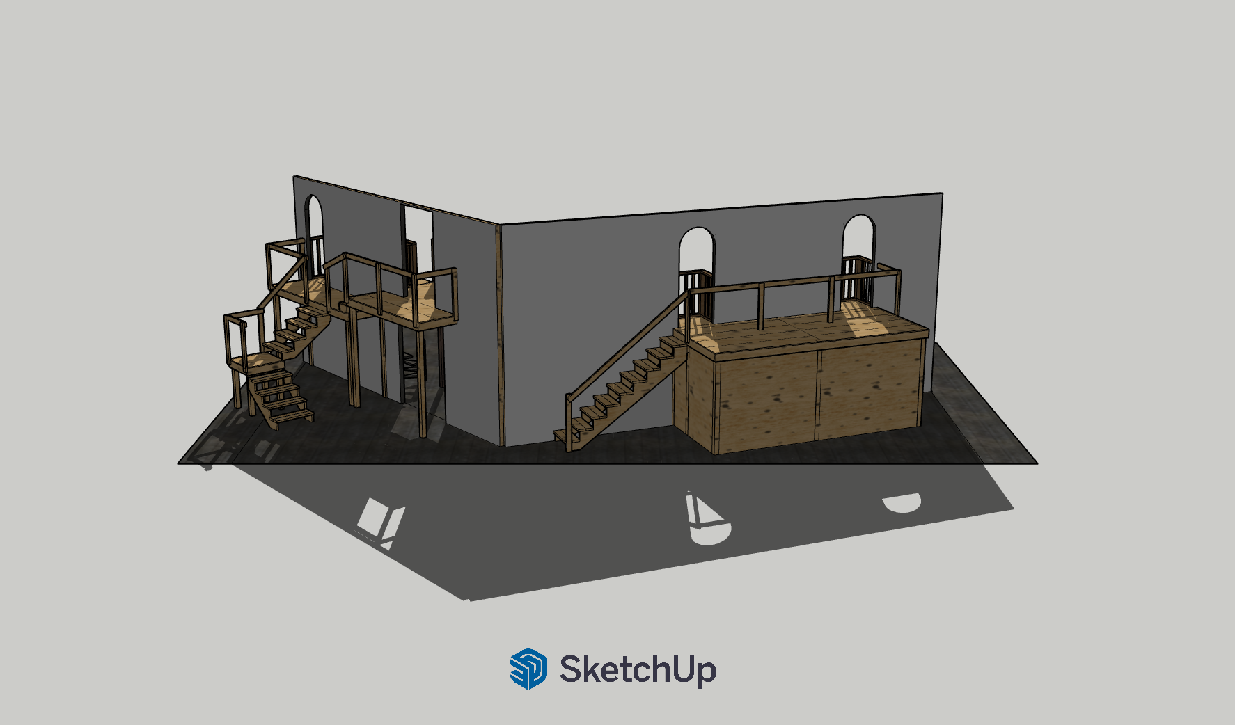
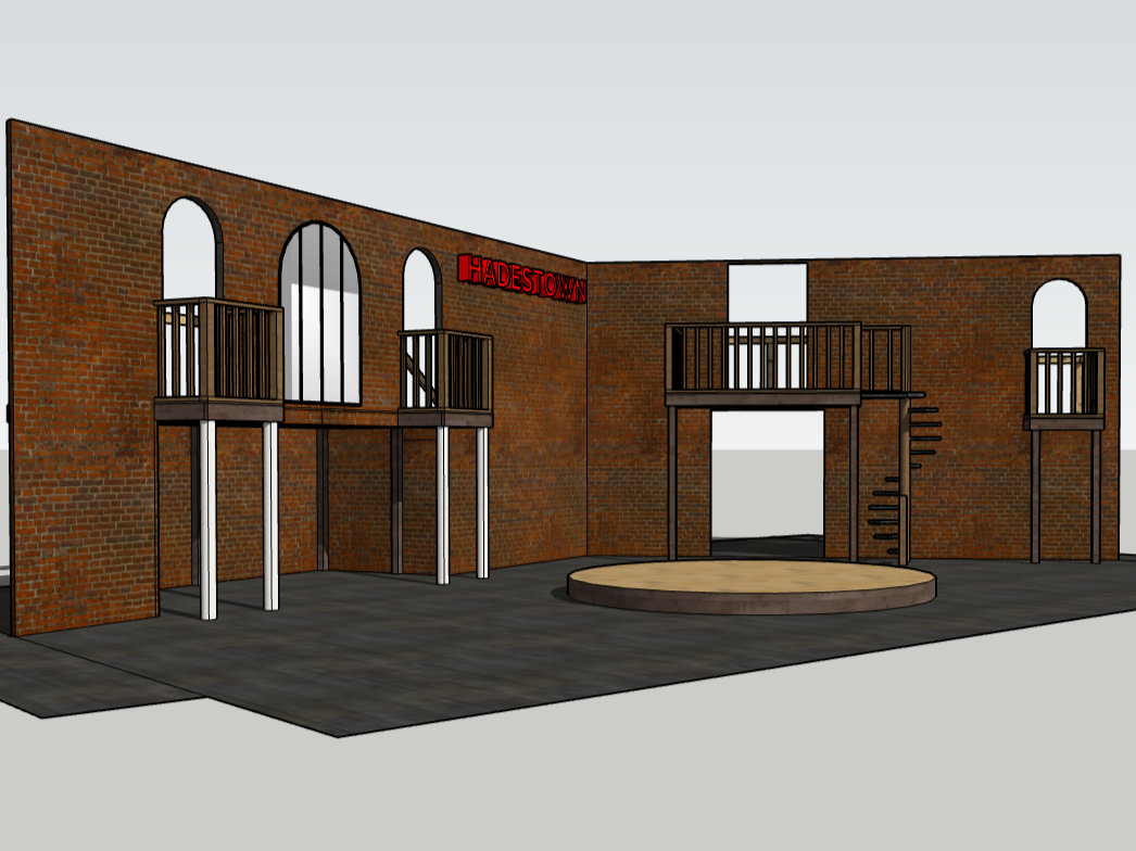
Finished 3D Model Rear
DESIGN DEVELOPMENT
The final scenic language developed around tall brick walls, arched industrial windows, elevated balconies, exposed structure, and a glowing HADESTOWN sign. Rather than recreating another production, I wanted the environment to establish its own visual identity while retaining the industrial character of the story.
The two angled walls created a shallow enclosure around the playing space without flattening the set into a conventional backdrop. Elevated platforms gave the cast additional performance levels, while openings throughout the architecture created routes for entrances, exits, and movement behind the scenery.
The central revolve became the visual and mechanical anchor of the design.
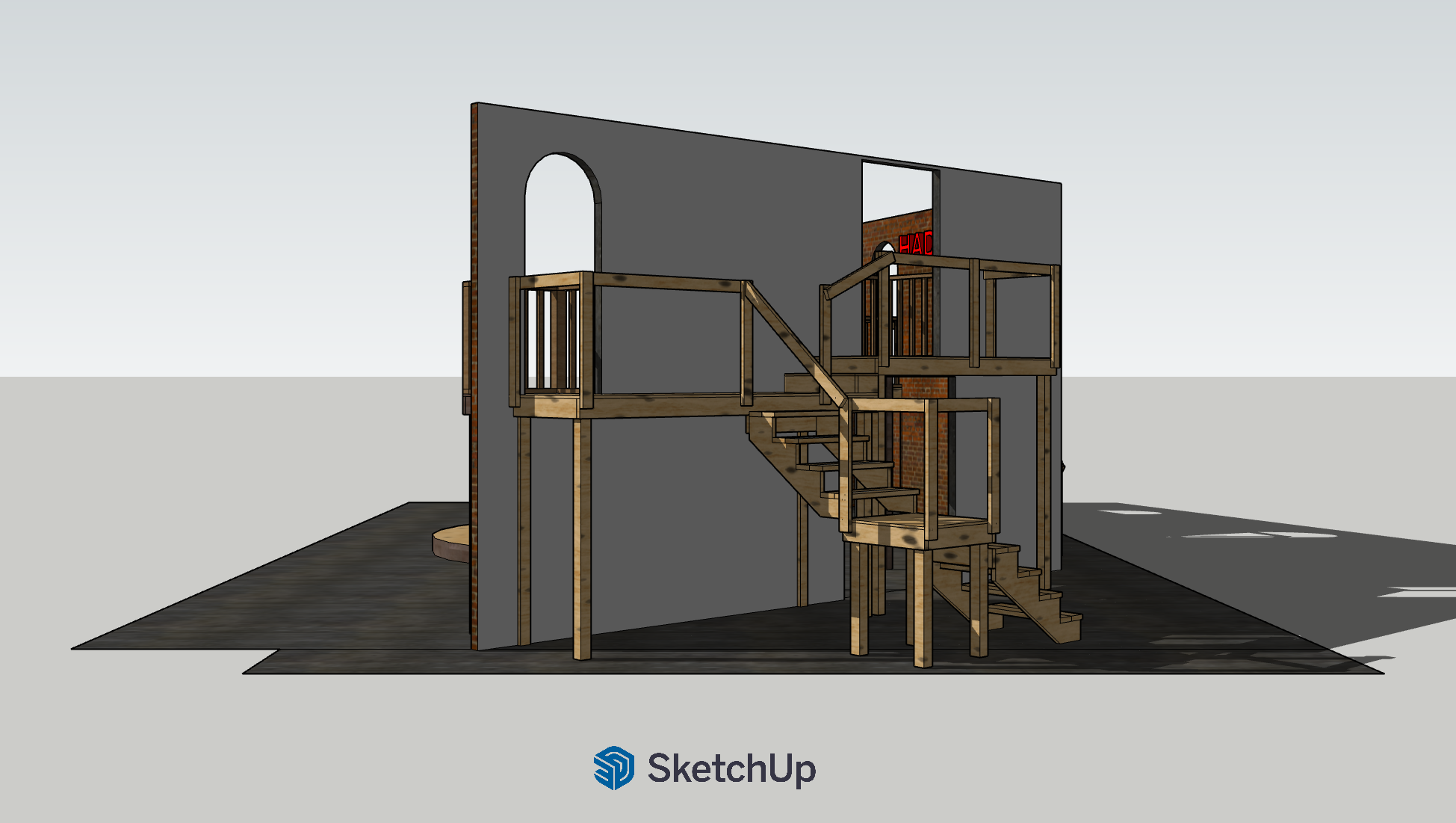
Finished 3D Model Right
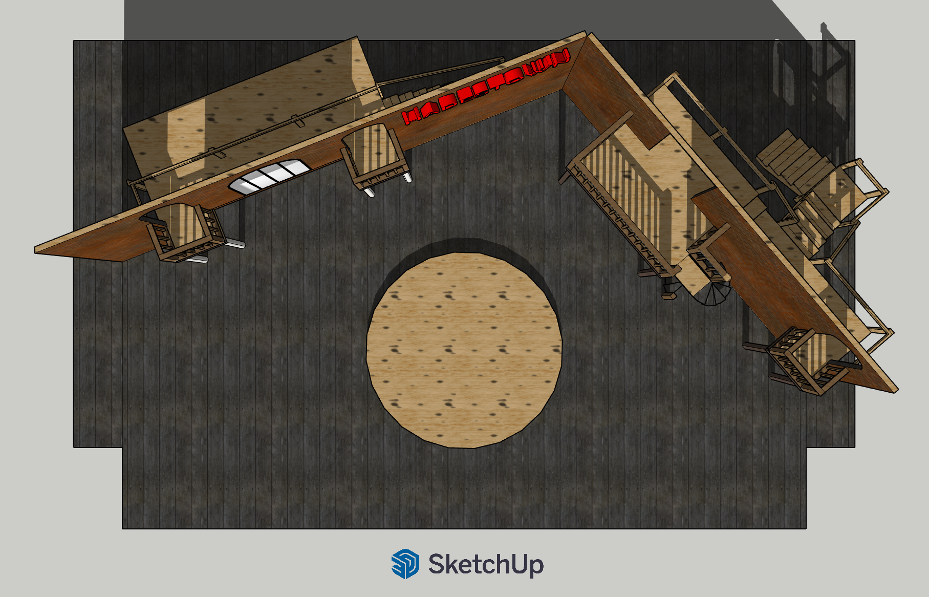
Finished 3D Model Top
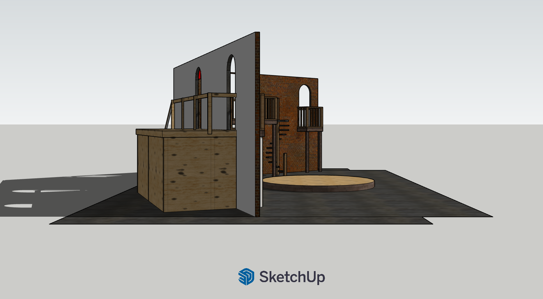
Finished 3D Model Left
ITERATION, NOT A FIRST DRAFT
Before settling on the final system, I explored multiple configurations for both the scenery and the revolve.
Early revolve concepts investigated different central hubs, radial framing arrangements, deck divisions, and methods of maintaining a stationary center while the surrounding 12-foot platform rotated. These studies helped determine how the platform could be fabricated in manageable sections while remaining rigid enough for performers.
What I was solving
STRUCTURE
How could a 12-foot platform support performers while remaining light enough to rotate?
MODULARITY
How could the platform be divided into sections that could actually be fabricated, assembled, serviced, and moved?
CENTER GEOMETRY
How could the outer platform rotate while the center remained stationary?
DRIVE
How could a motor move the platform smoothly and slowly enough for choreography without becoming visually or acoustically distracting?
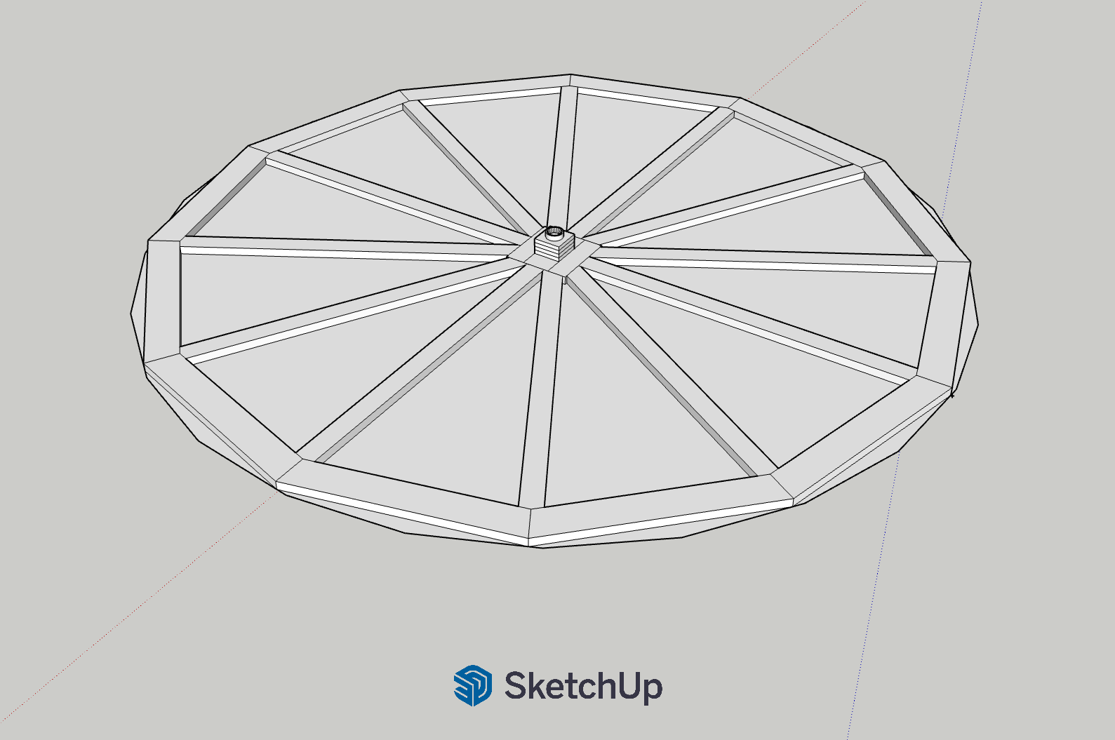
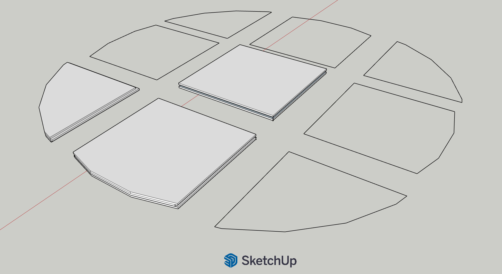
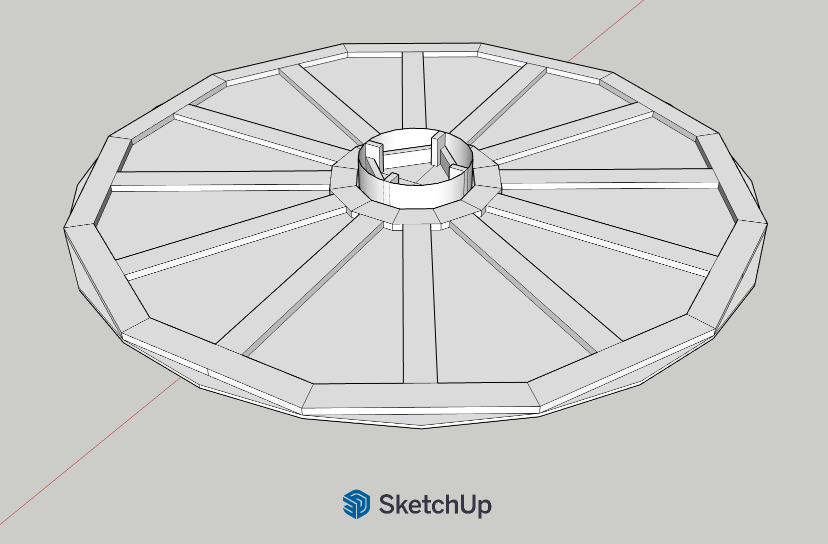
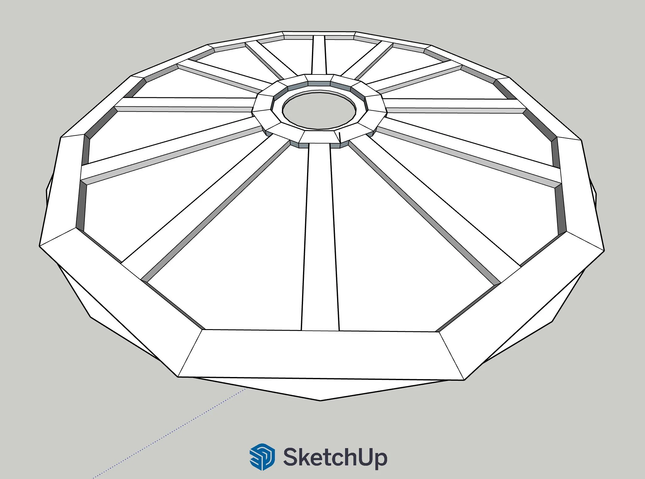
ENGINEERING THE REVOLVE
A scenic element became a machine.
The revolve required far more than a rotating piece of scenery. It became a complete mechanical system that had to carry live performers, start and stop predictably, operate at variable speeds, run in both directions, and survive repeated rehearsals and performances.
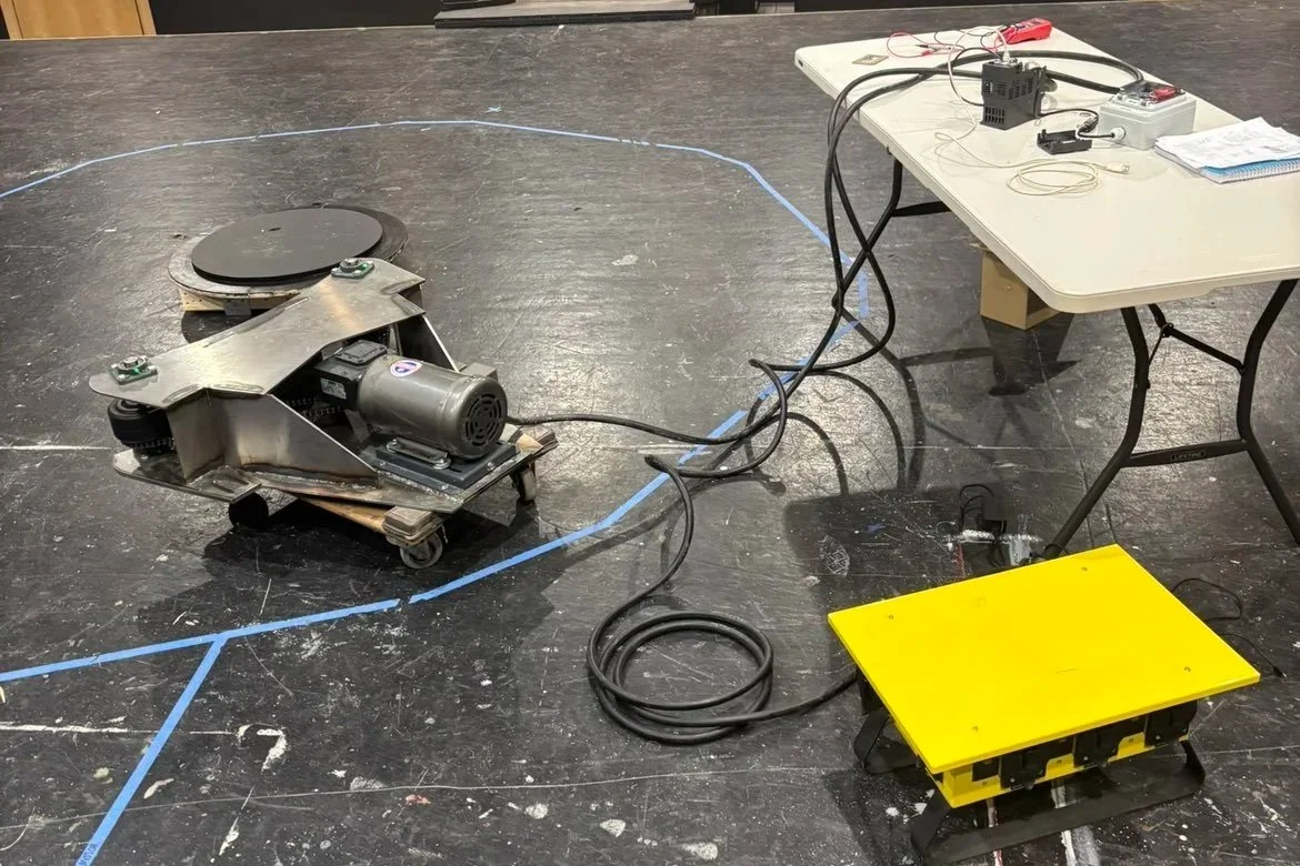
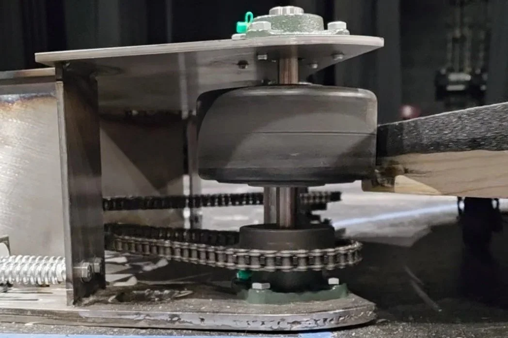
I developed a radial structural frame supporting a segmented circular deck and designed the system around a stationary center. The rotating assembly was ultimately driven through a motor, worm-gear reducer, chain transmission, and traction-drive system.
A variable-frequency drive provided control over motor speed and direction, allowing the movement to be adjusted to the pacing and choreography of individual scenes.
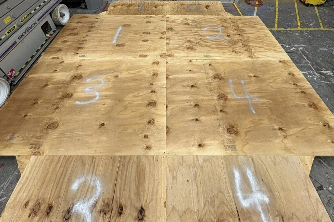
Initial Plywood Sheet Layout
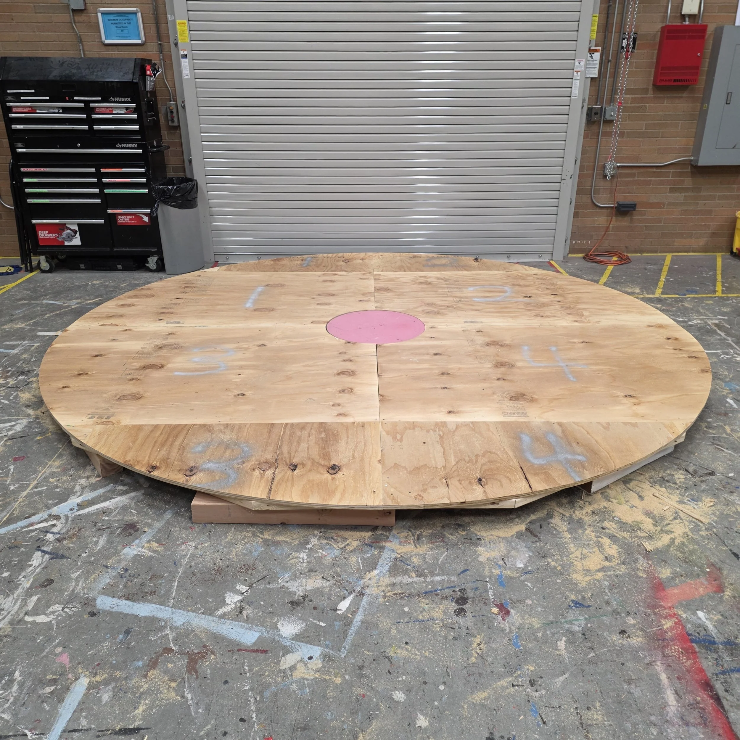
Plywood Sheets Cut to Final Circle
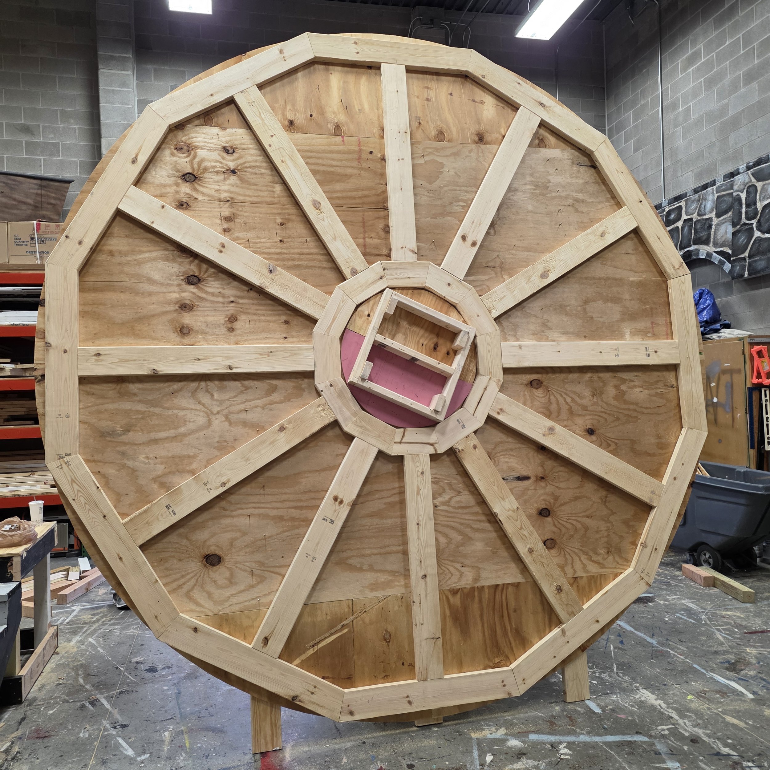
Bottom Framed and Assembled to Top
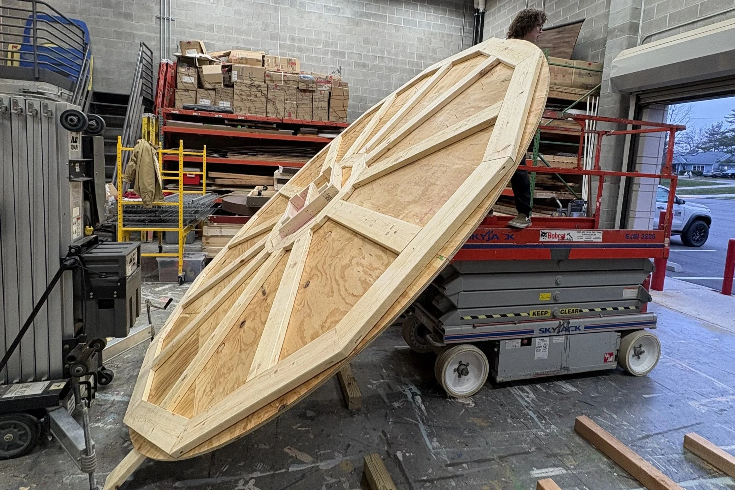
Flipping Structure to Install Wheels
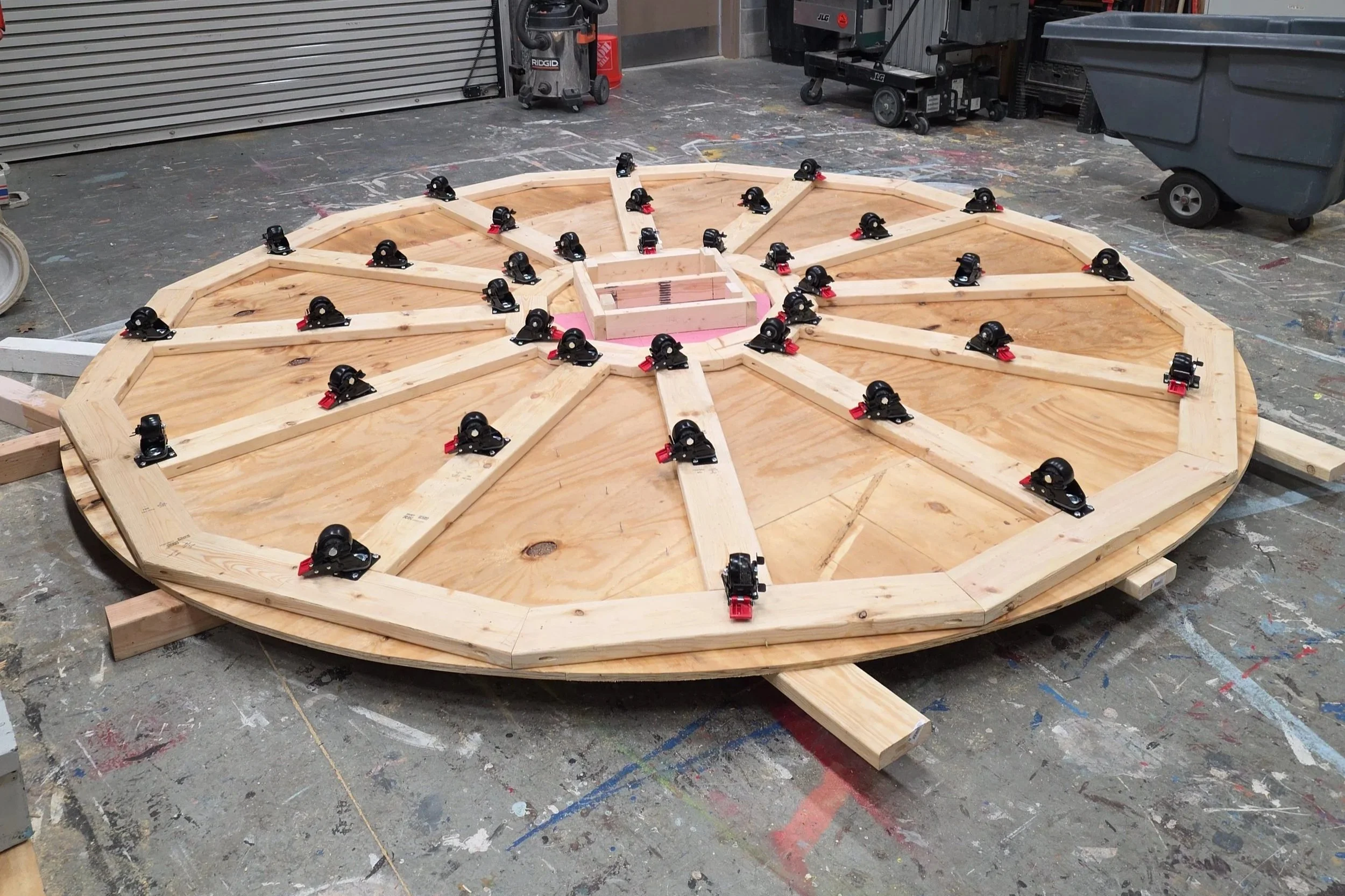
Wheels Installed
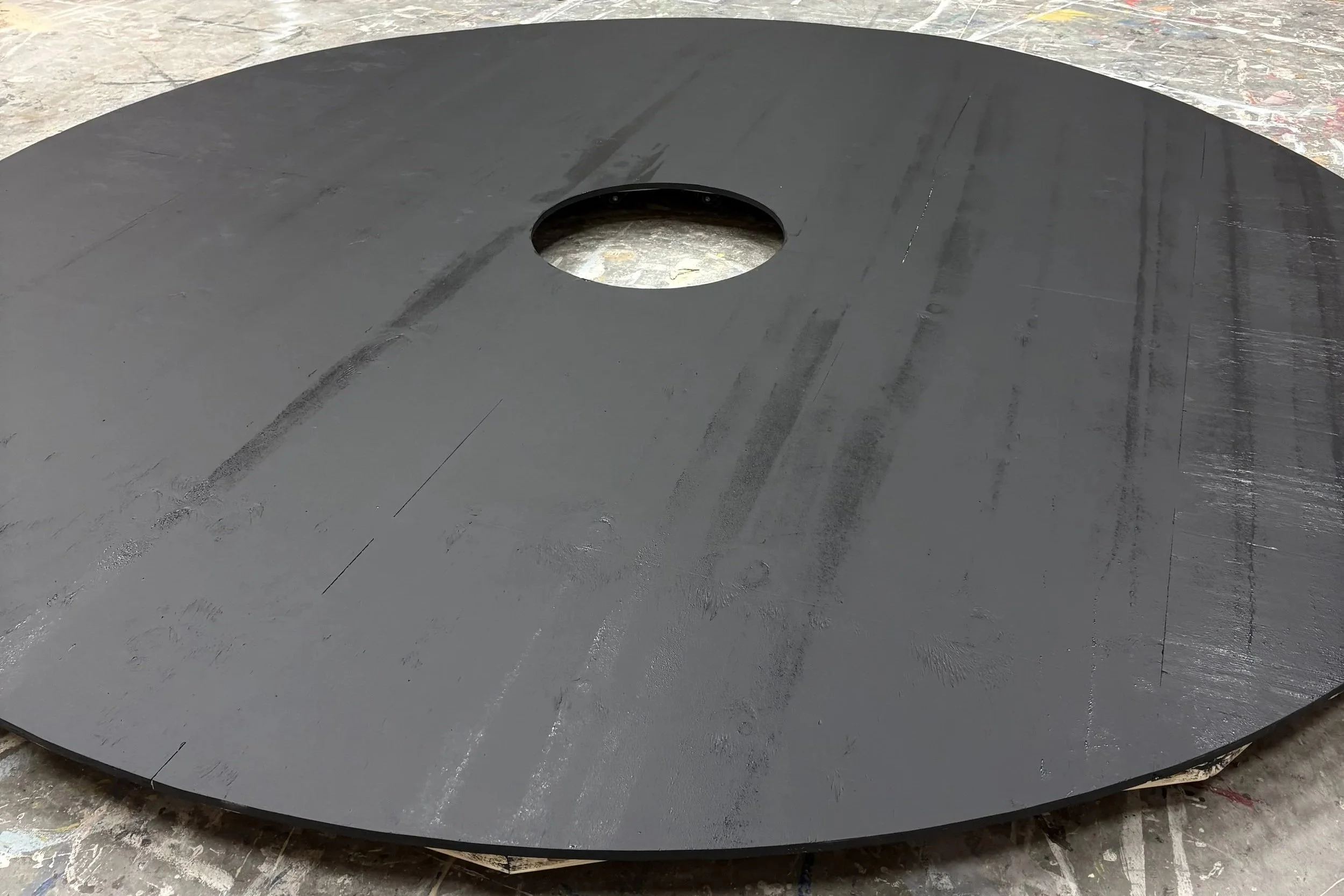
Top Painted
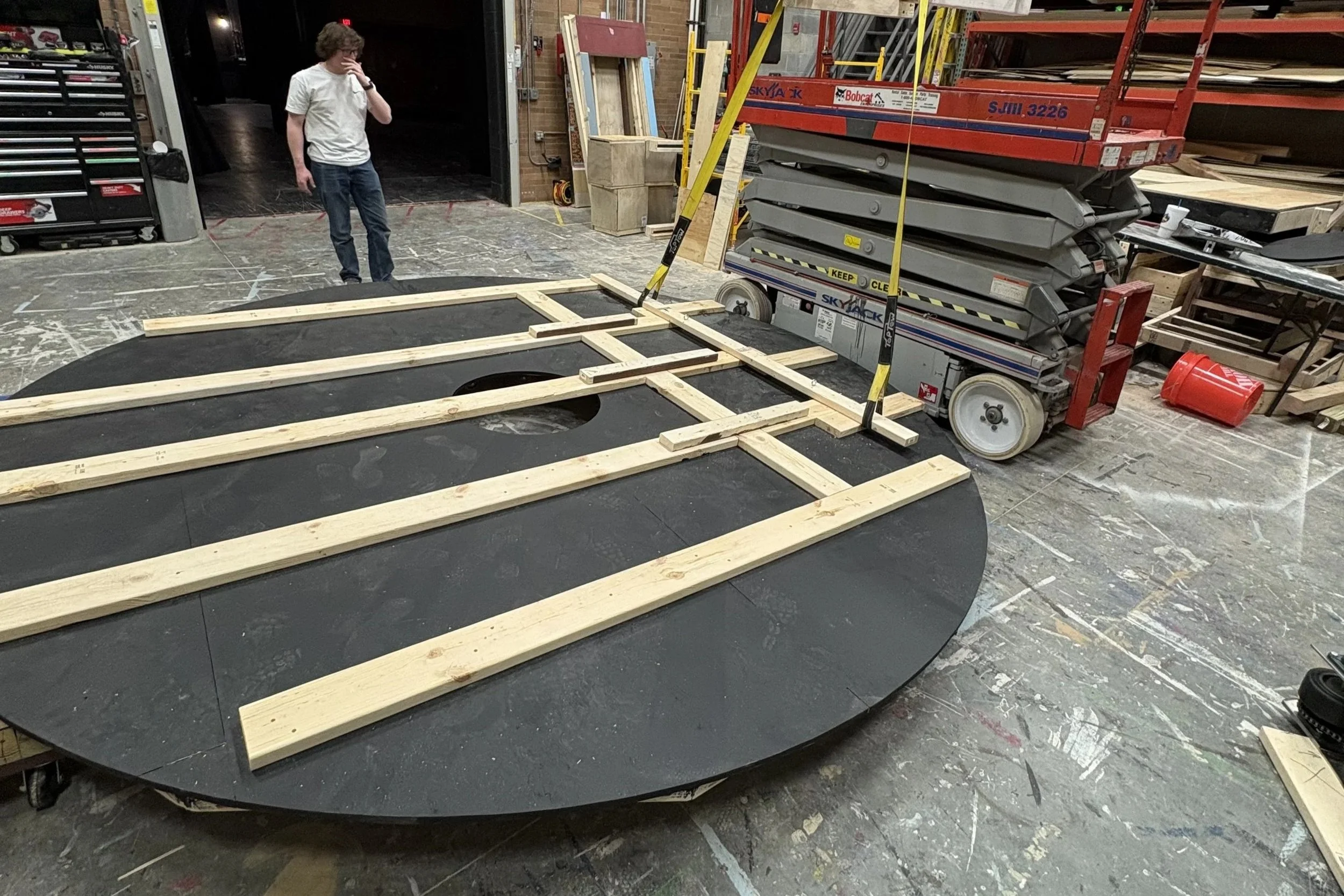
Top Framed with Supports for Load-in
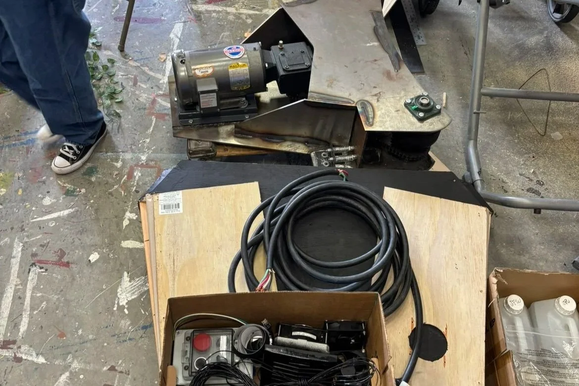
Drive Motor Assembly and Controller Components
Programming Controller
Drive System and Revolve First Tests
DESIGNING THROUGH FAILURE
The first solution was rarely the final solution.
Building the revolve required continuous testing and redesign. Problems that were invisible in CAD became obvious once the mechanism was operating at full scale.
The drive system went through multiple revisions as I worked through motor mounting, fixed chain-center distances, sprocket alignment, traction, noise, and control behavior. One major fabrication issue came from a mismatch between the selected motor mounting configuration and the reducer interface, requiring the drive assembly to be reconsidered rather than simply bolted together as originally planned.
The chain transmission introduced another constraint: both sprockets operated on fixed centers, so chain length, sprocket geometry, alignment, and tension had to work as a complete system.
Traction between the drive wheel and the revolve also became an iterative problem. Early solutions did not provide the combination of grip, compliance, and quiet operation that the production required. Testing eventually led to a rubber interface that improved contact while reducing mechanical noise.
This process changed the project from something I had drawn into something I actually understood.
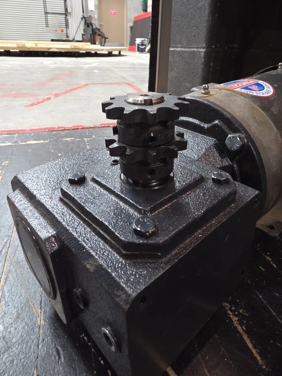
Stacked Sprockets on Single Shaft
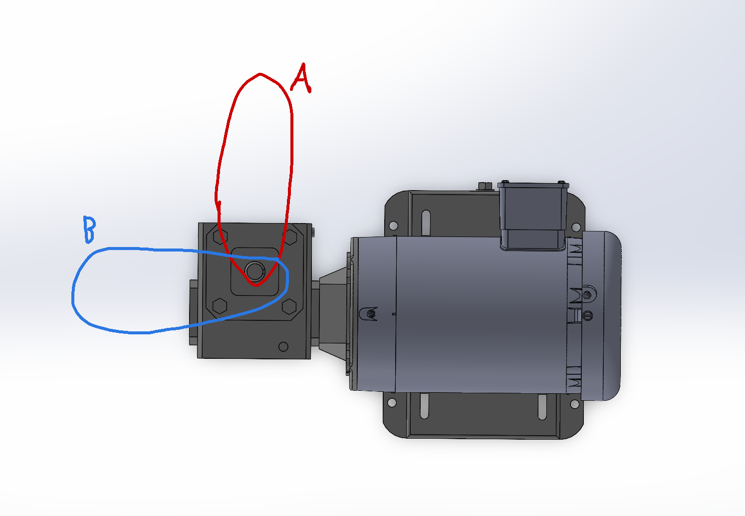
Exploring Chain Length Variation Tolerance
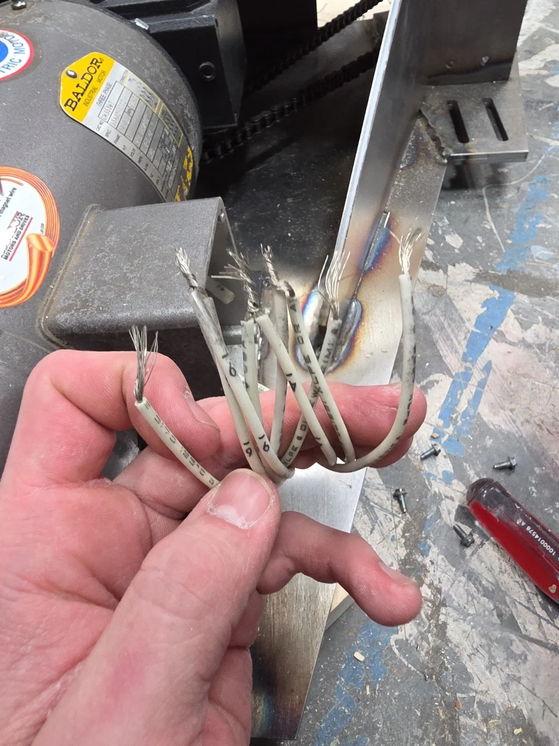
Missing Wiring Diagram Plate on Motor
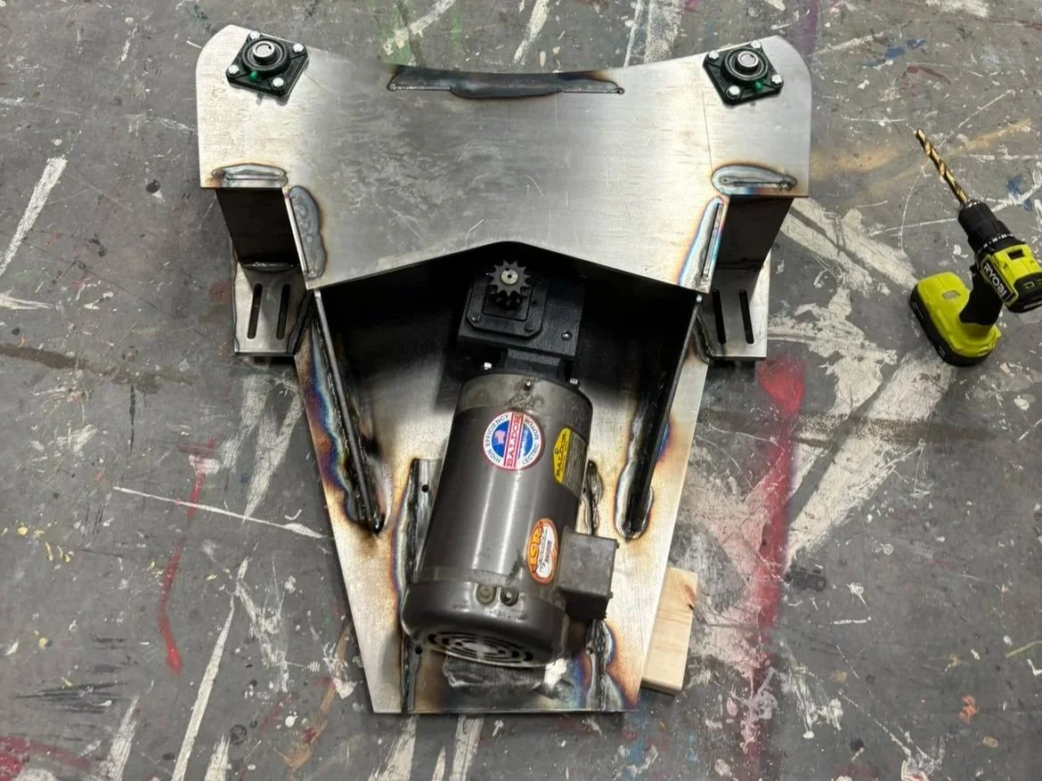
Original Motor Mount Required Modification
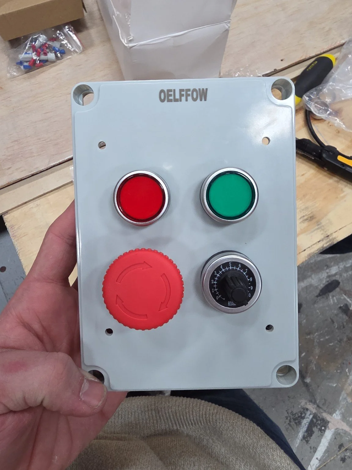
Controller Buttons Had to be Changed to Switches
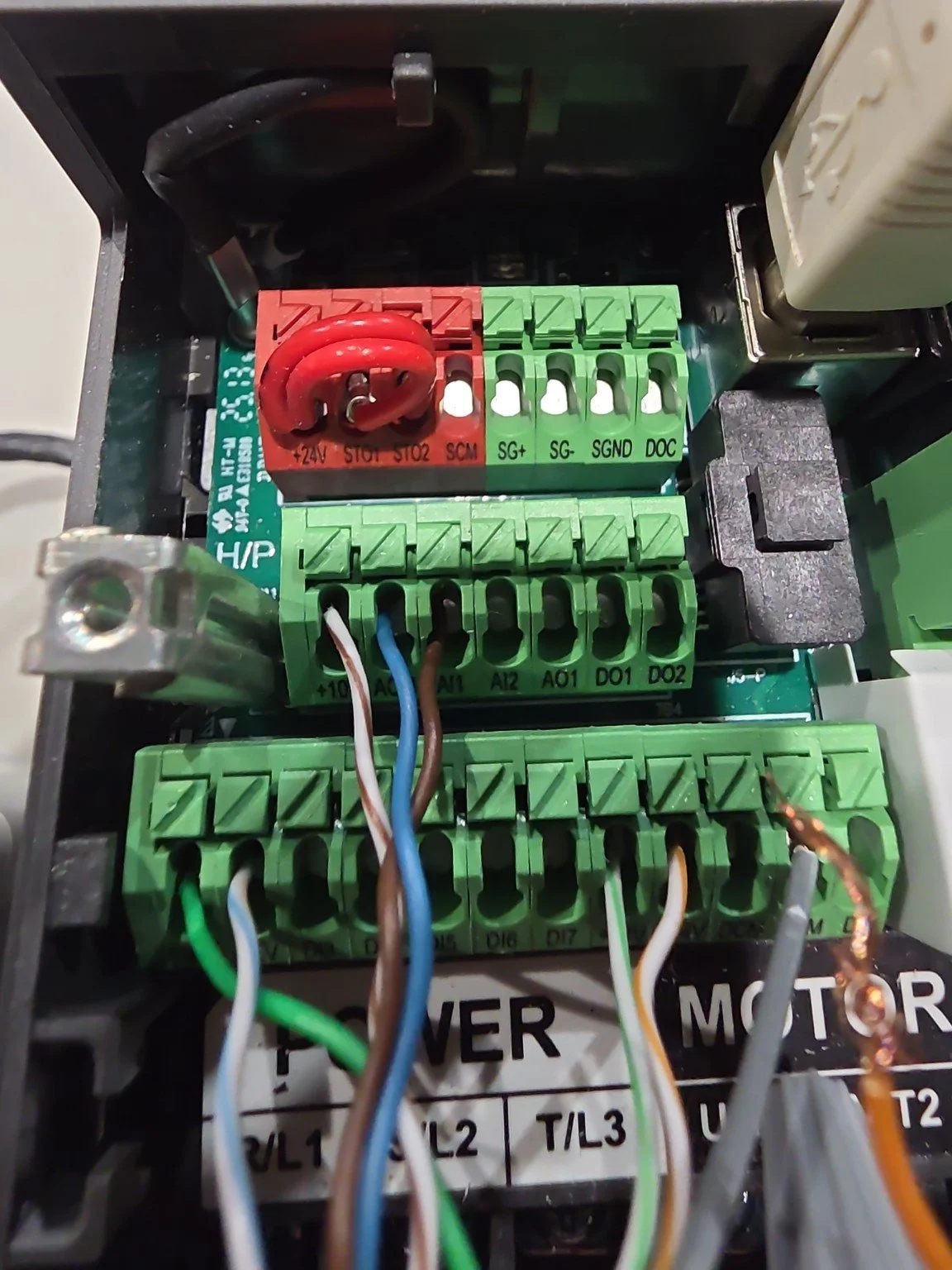
STO System Initially Wired Incorrectly
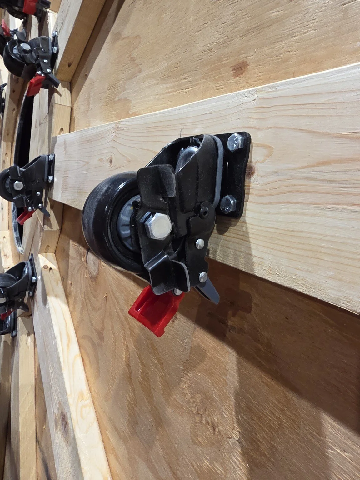
Multi-position Caster Brakes Created Noise
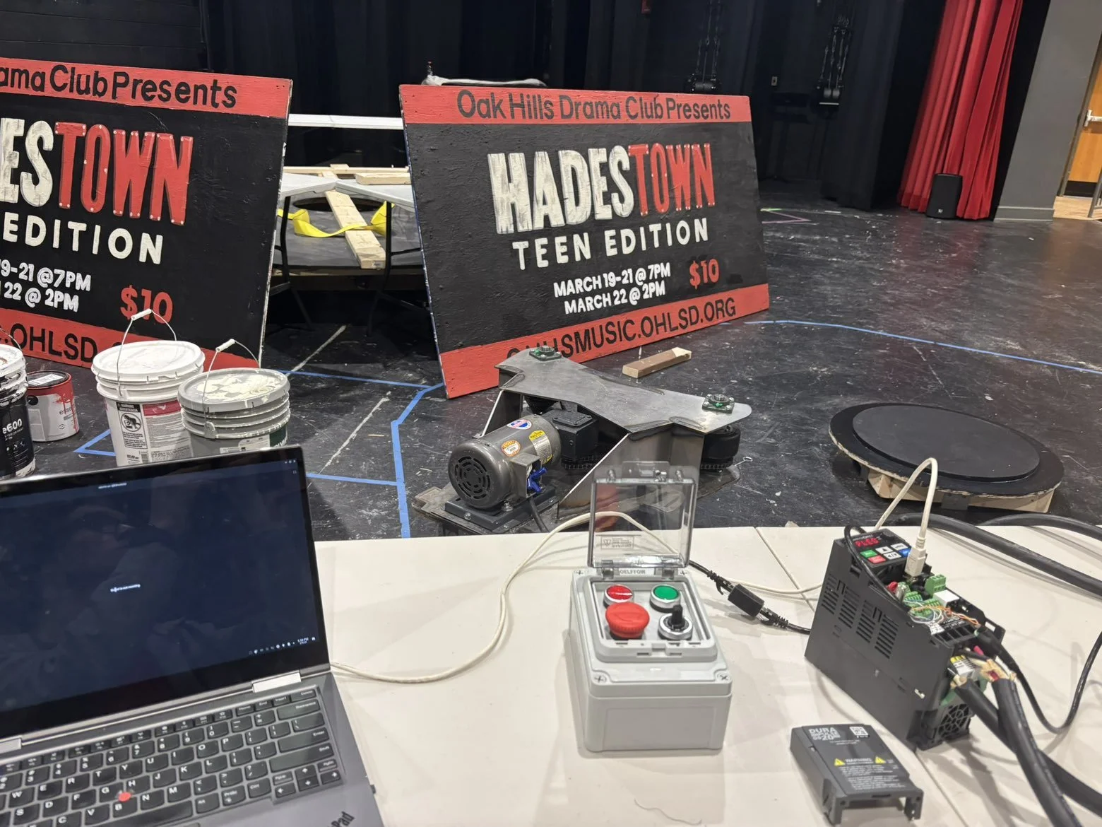
Controller Switches and Potentiometer Programming
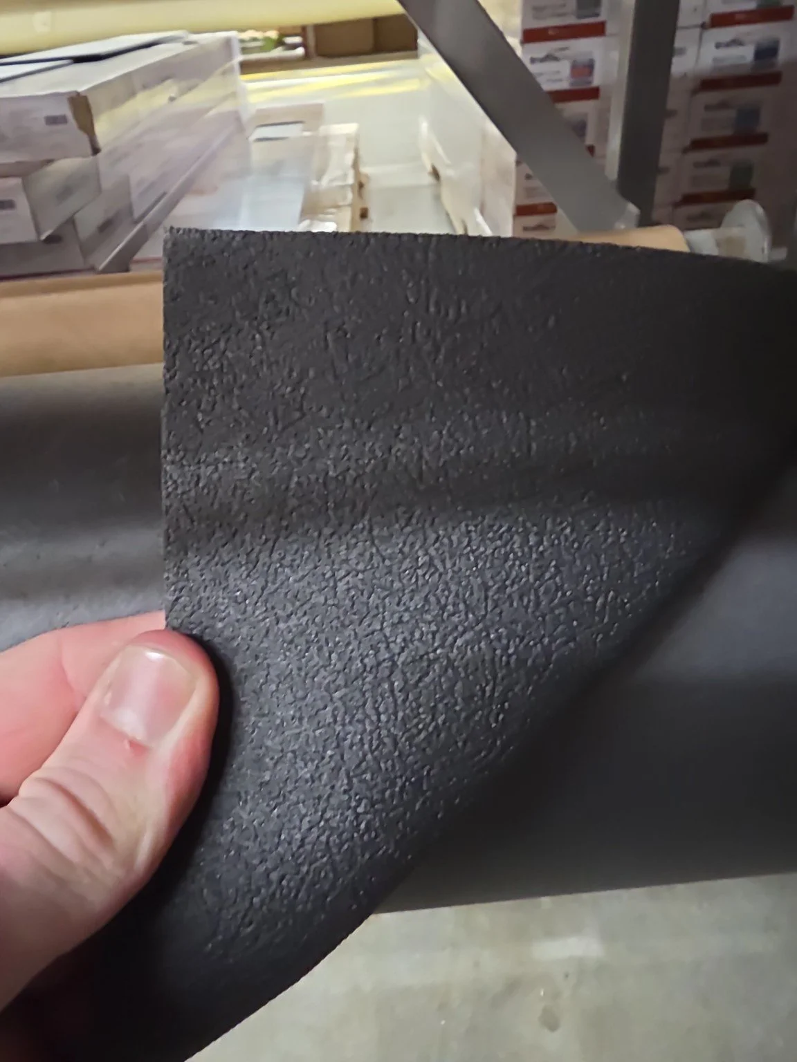
Changing Grip-tape Traction Material for Rubber
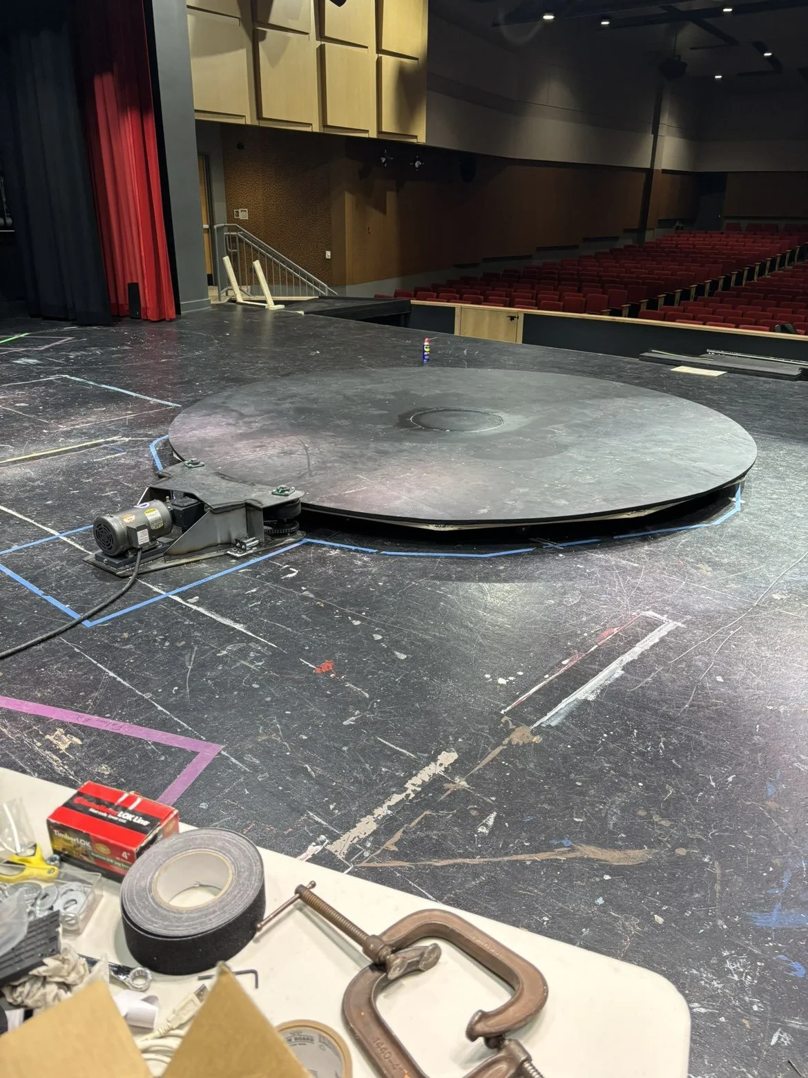
Troubleshooting Final Turntable Assembly
CONTROLS & SAFETY
Because performers would be standing on the platform during operation, the control system had to do more than simply switch a motor on and off.
I configured the VFD for externally commanded forward, reverses and speed operations and developed a remote operator controller so the revolve could be controlled independently during the production.
The emergency-stop circuit was later revised to use the VFD's Safe Torque Off (STO) inputs as a dual-channel safety function. Activating any of the three E-stop buttons throughout the set removed the motor's ability to generate torque without relying solely on a conventional software stop command. Cast and crew were diligently informed on the locations of the E-stops, as well as how and when to operate them.
Because the operator could not maintain a direct view of the platform from the control position, I also implemented a three-camera monitoring system to provide visibility around the revolve during operation.
The result was not just a moving platform, but an integrated scenic, mechanical, electrical, and operational system.
Operator → Controller → VFD → Motor → Gear Reducer → Chain → Traction Wheel → Turntable
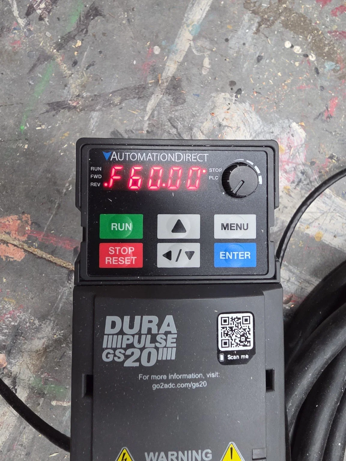
Initial Testing with VFD Stop as Only Safety
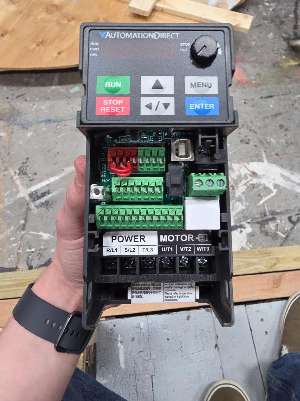
Figuring Out How the STO Wiring Works
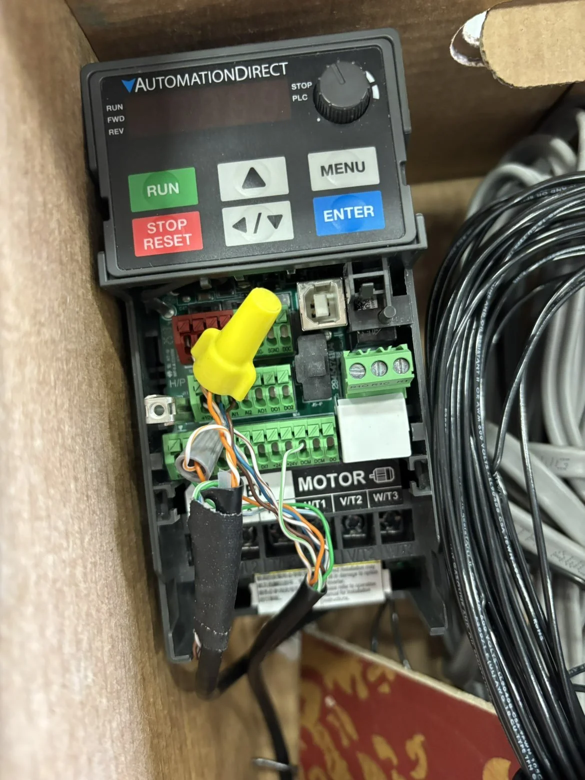
Wiring STO Lines to VFD Terminals
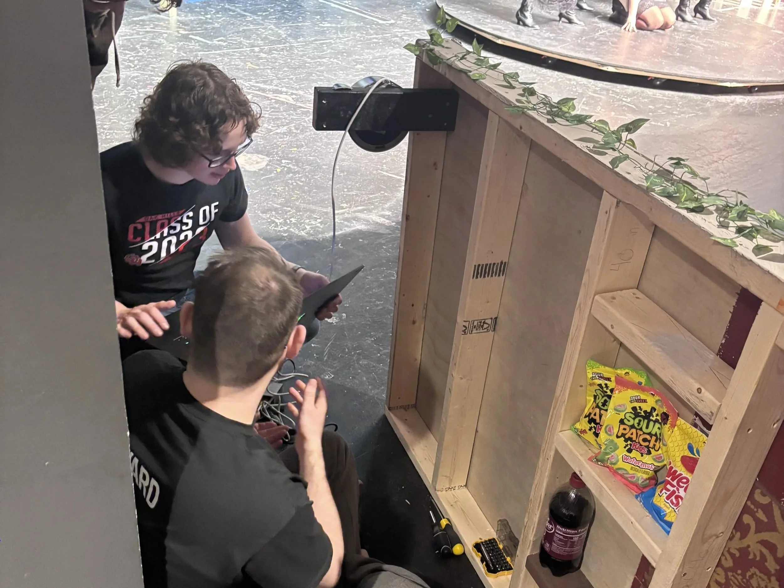
Installing Live-view Cameras
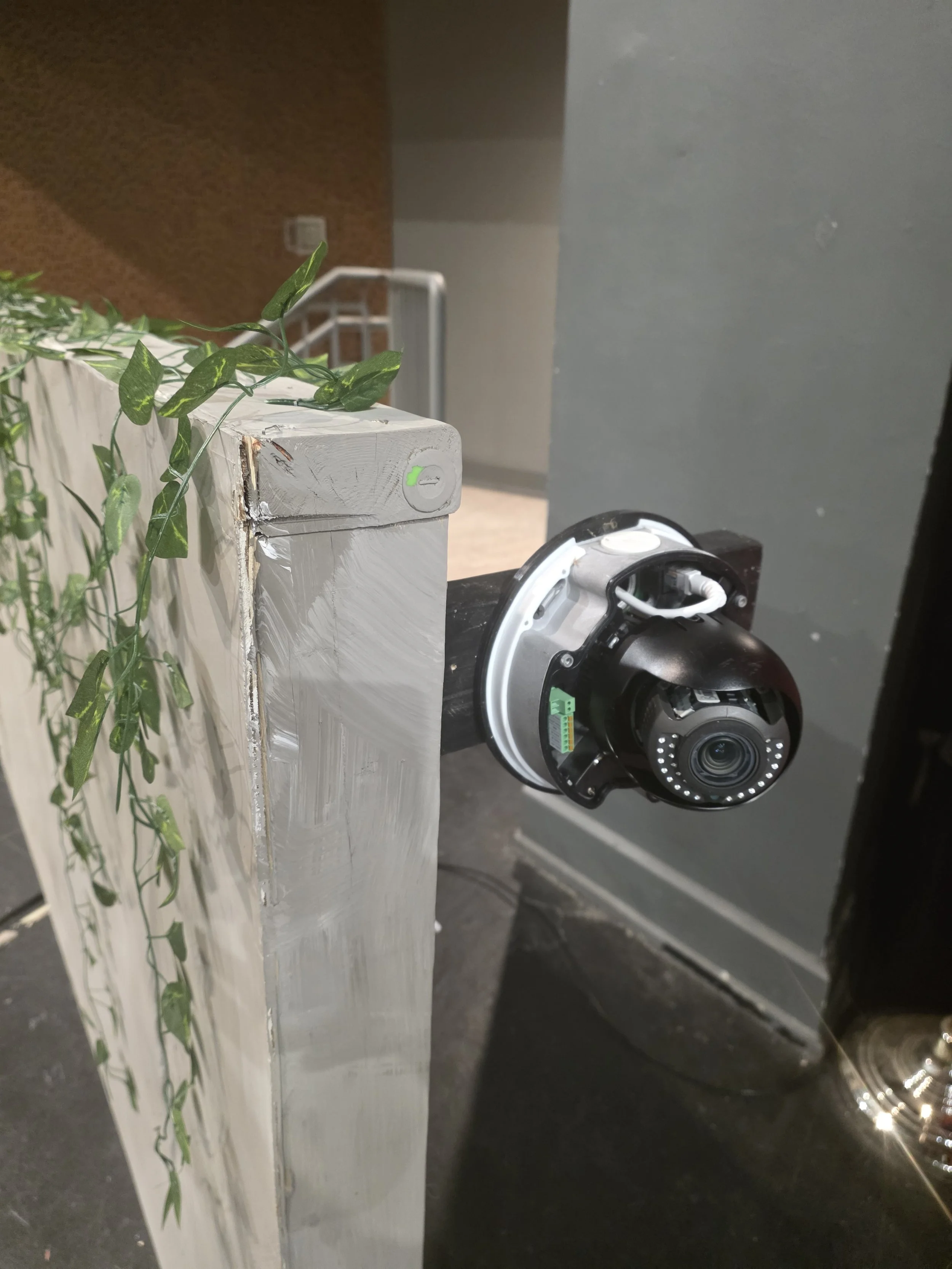
Installed Camera

Installing Live-view Monitor at Operator's Desk
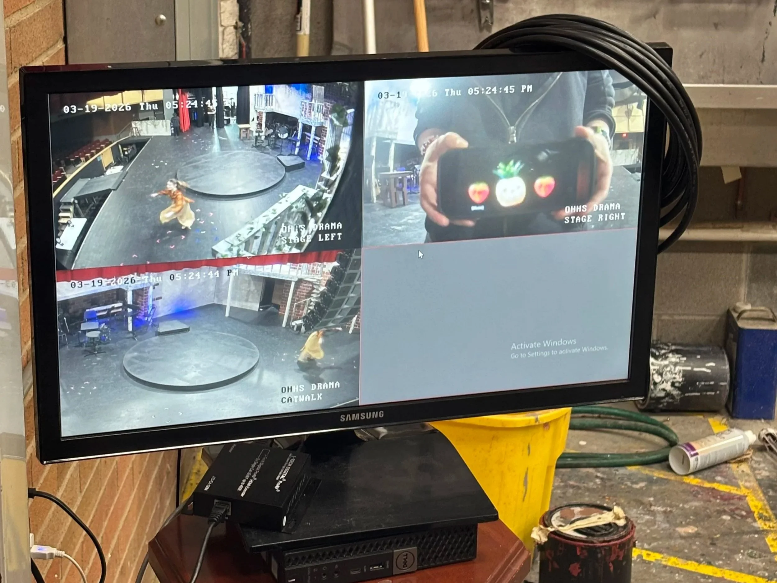
Additional Live-view Monitor for Stage Manager
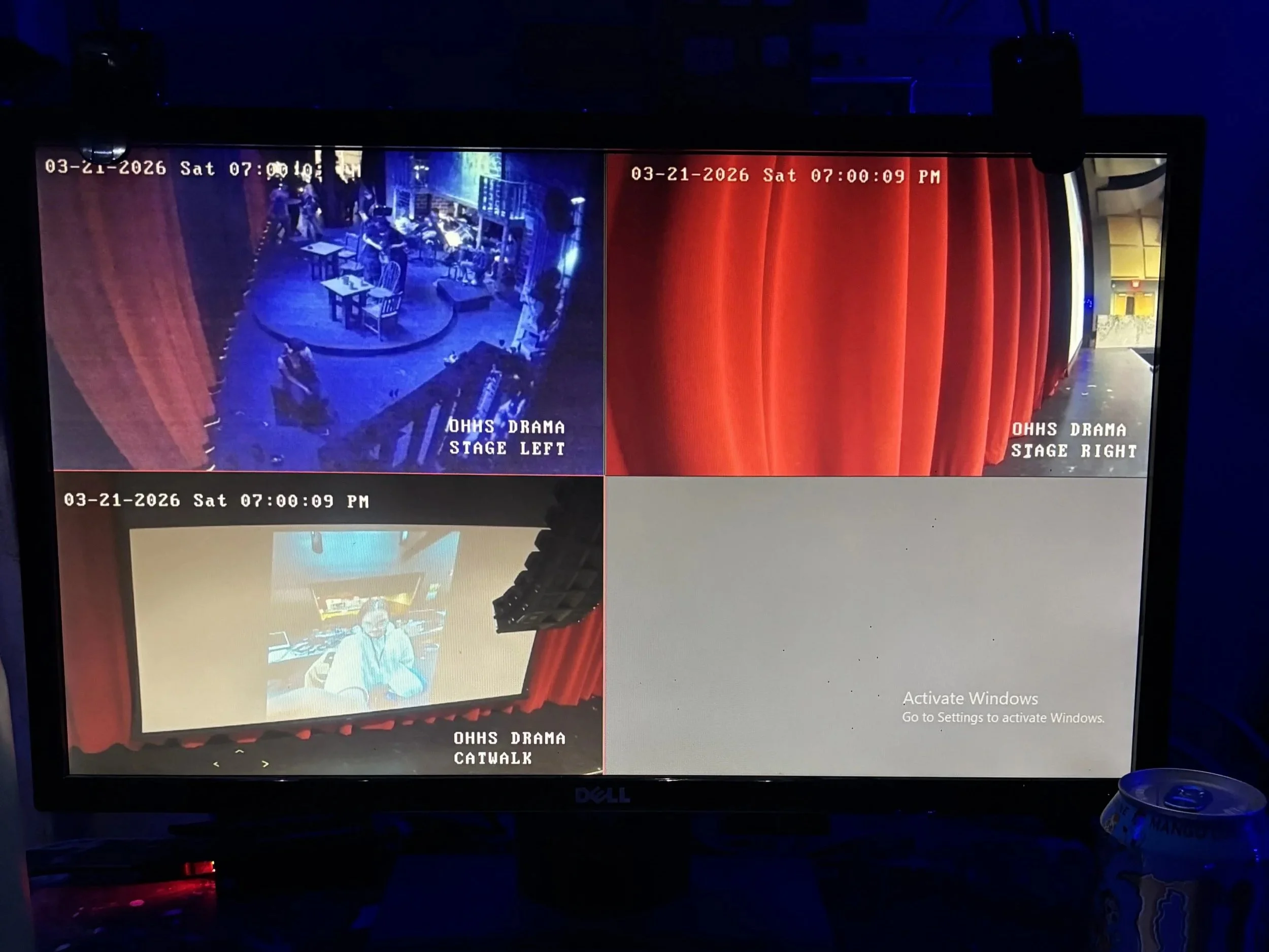
Live-view From Cameras Pre-performance
FABRICATION
Once the design was resolved, the project moved from digital modeling into full-scale fabrication.
The scenic environment combined conventional theatrical construction with the much tighter tolerances required by the mechanical system. Walls, platforms, balconies, stairs, railings, and architectural details had to integrate around the revolve while preserving performer circulation and backstage access.
The revolve itself combined a fabricated structural frame with a segmented deck, central support system, drive components, and removable surfaces that allowed the mechanism to remain accessible during testing.
The build became an ongoing loop:
Model → Fabricate → Assemble → Test → Diagnose → Modify → Test again
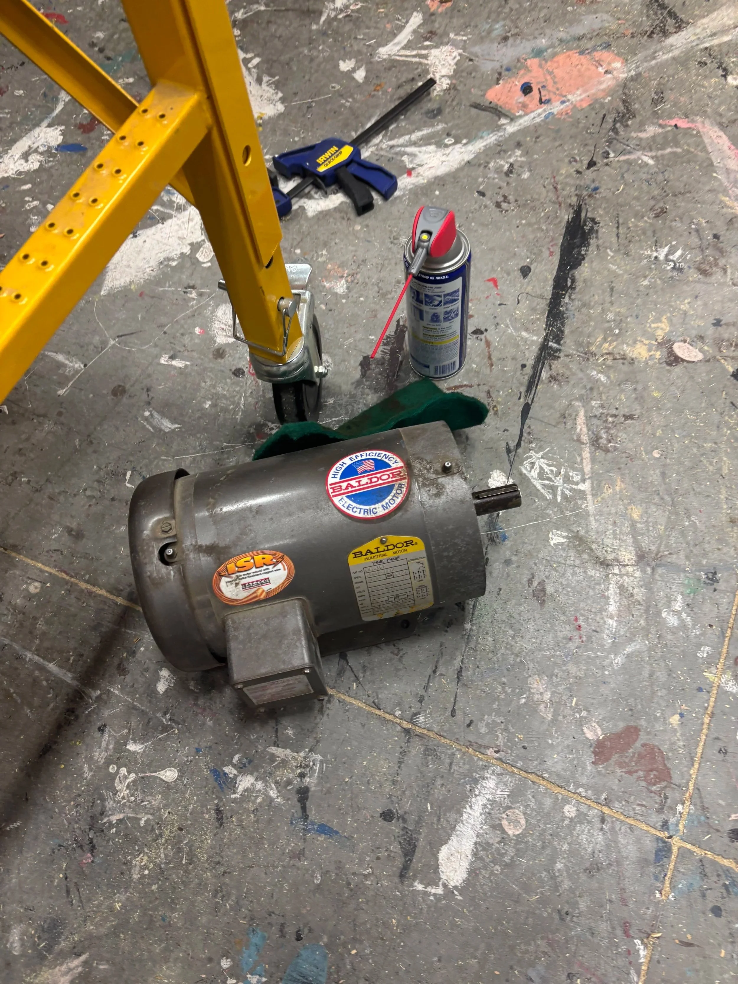
Cleaning Motor Output Shaft
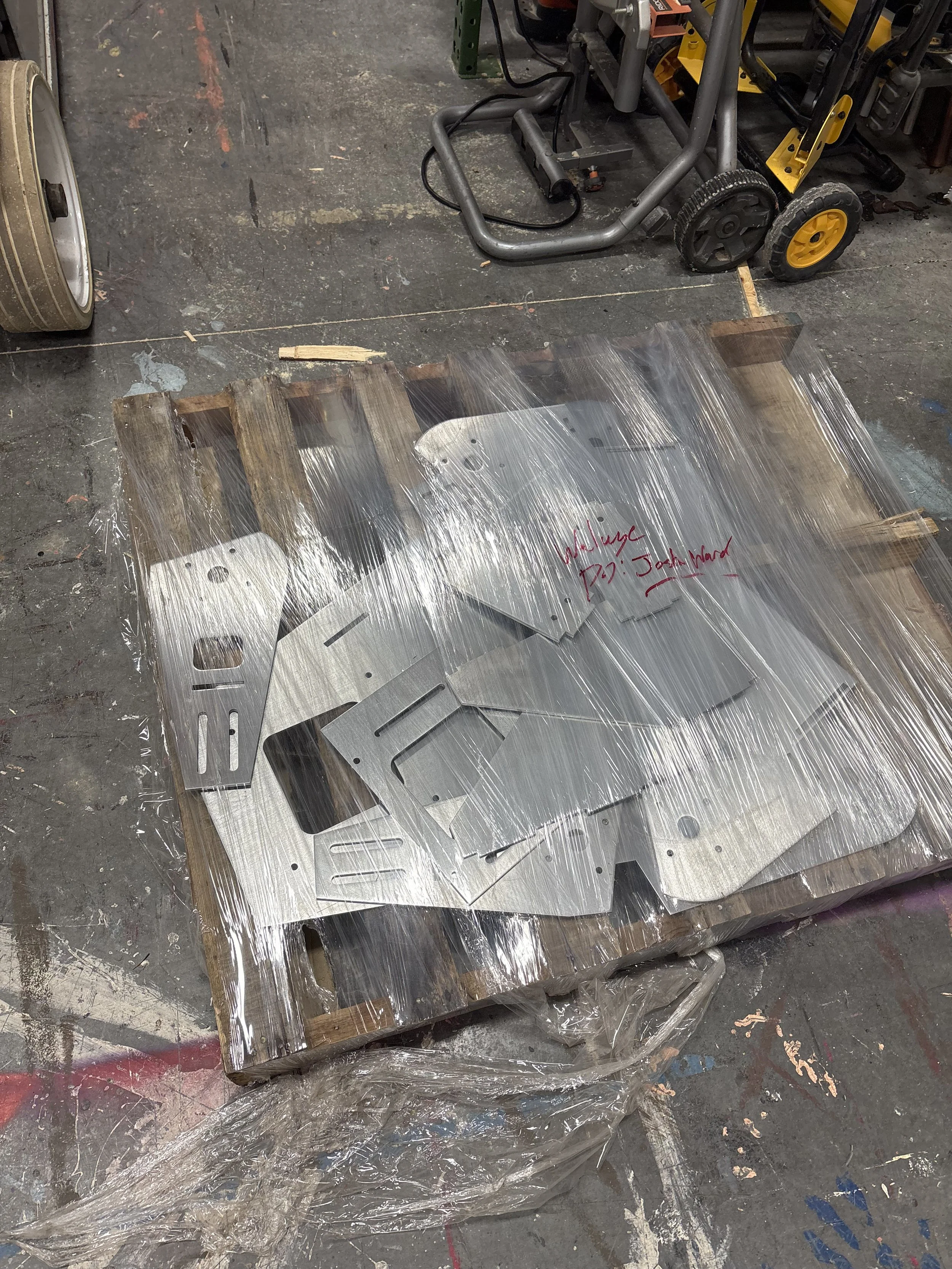
Traction Drive Frame Pieces Arrived
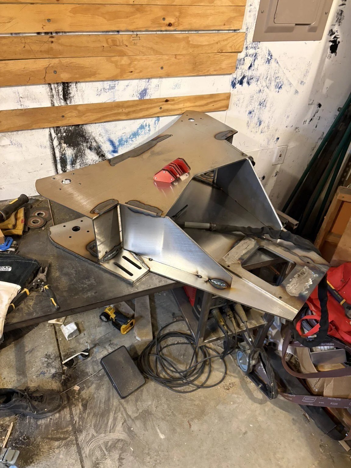
Frame Welded Together (credit to Hayes Ryland)
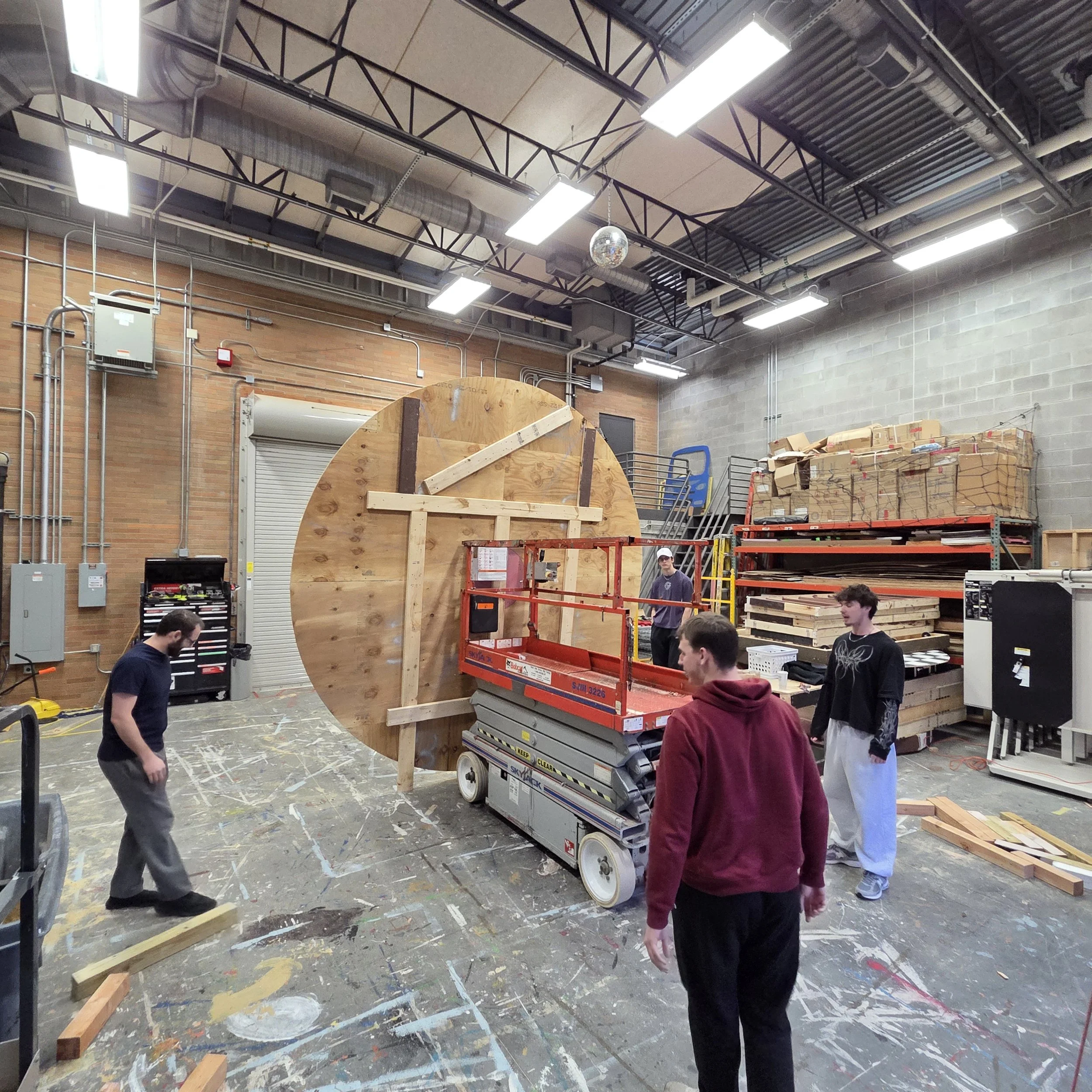
Preparing Turntable for Load-in
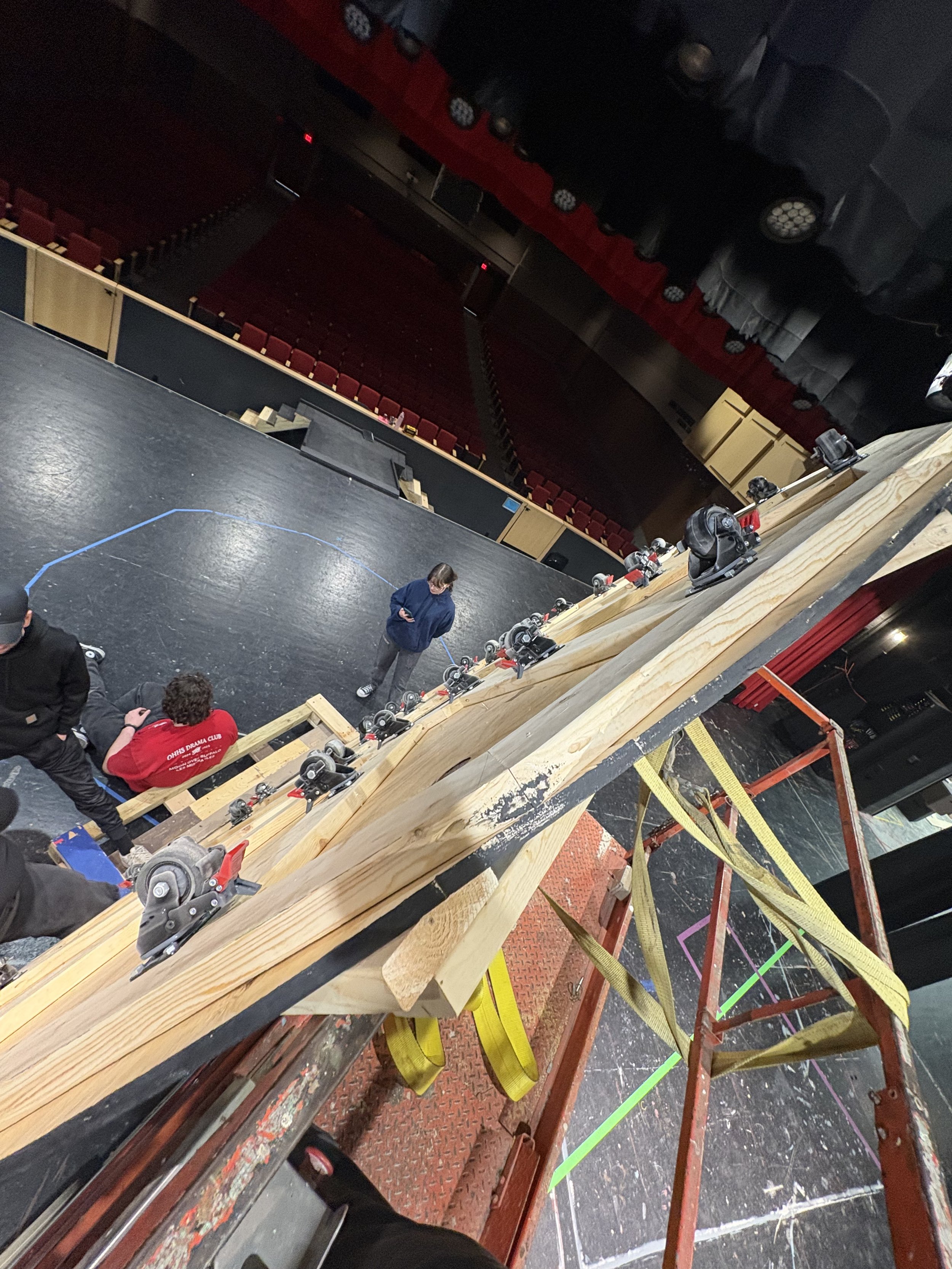
Loading in the Turntable
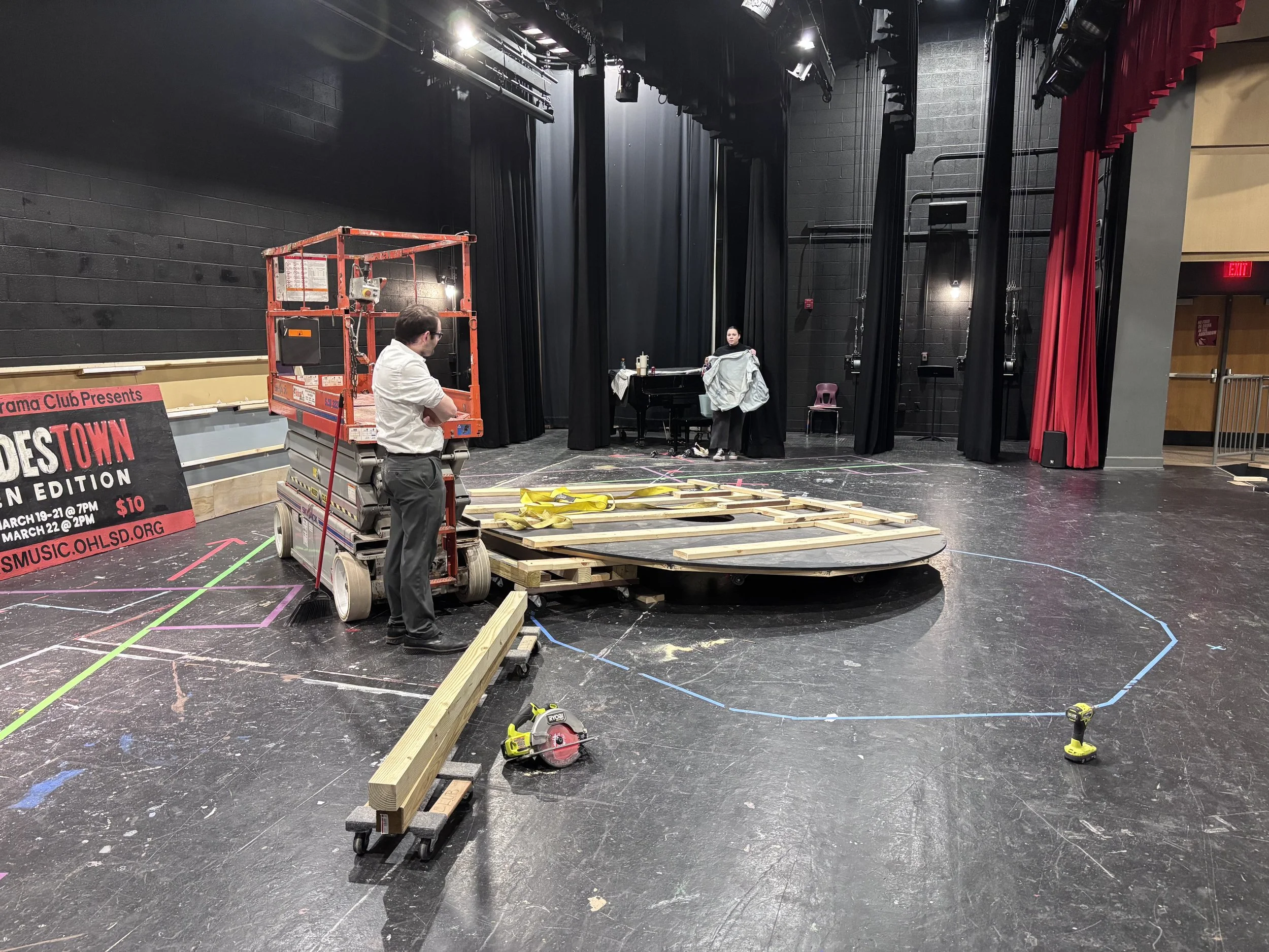
Turntable on Deck
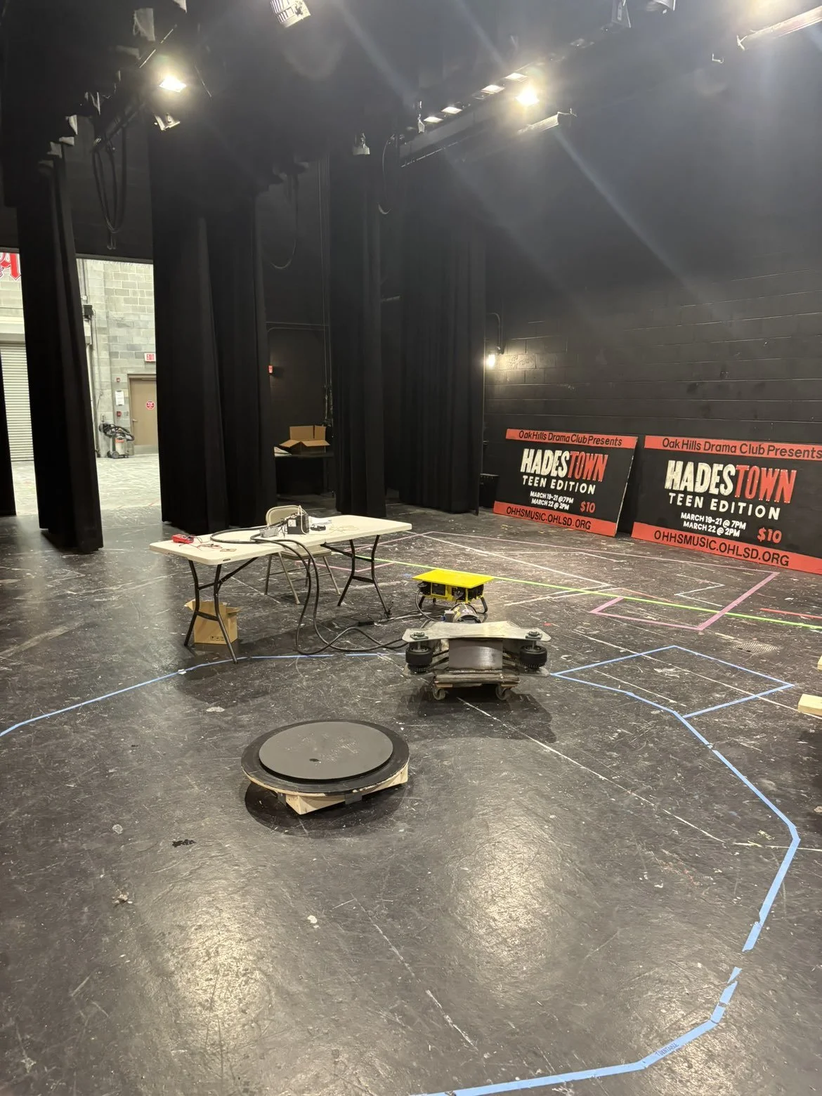
Placing Center Turntable Platform
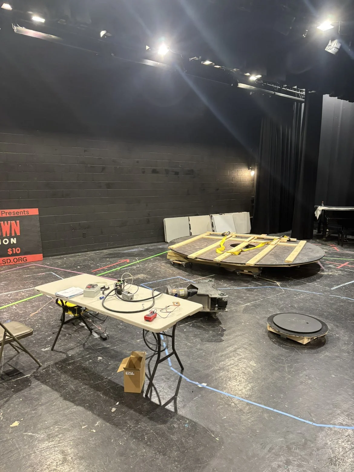
Programming Drive System Before Mounting Turntable
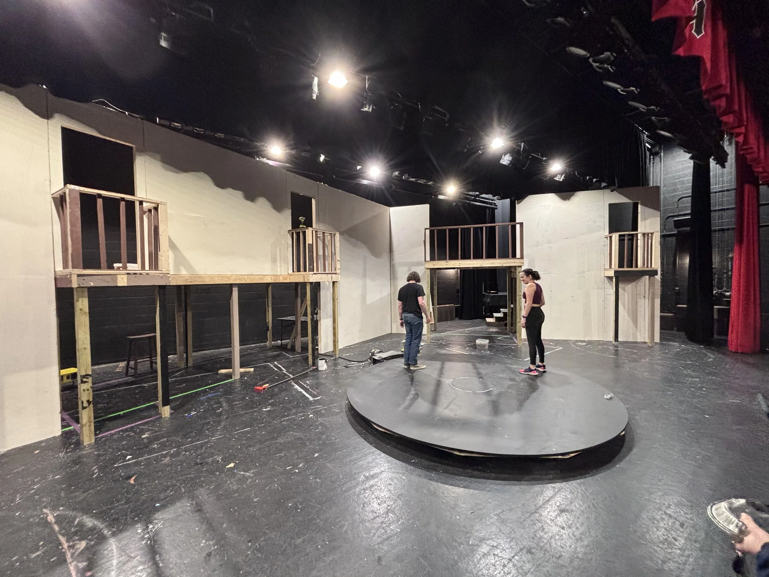
Set Construction Begins Around Turntable
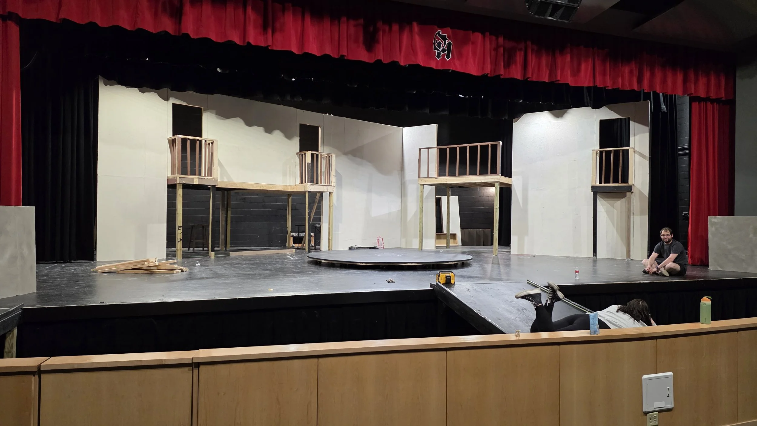
Construction into Orchestra Pit Begins
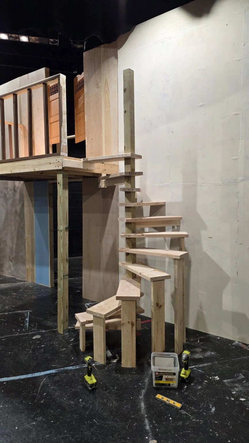
Spiral Staircase Installed
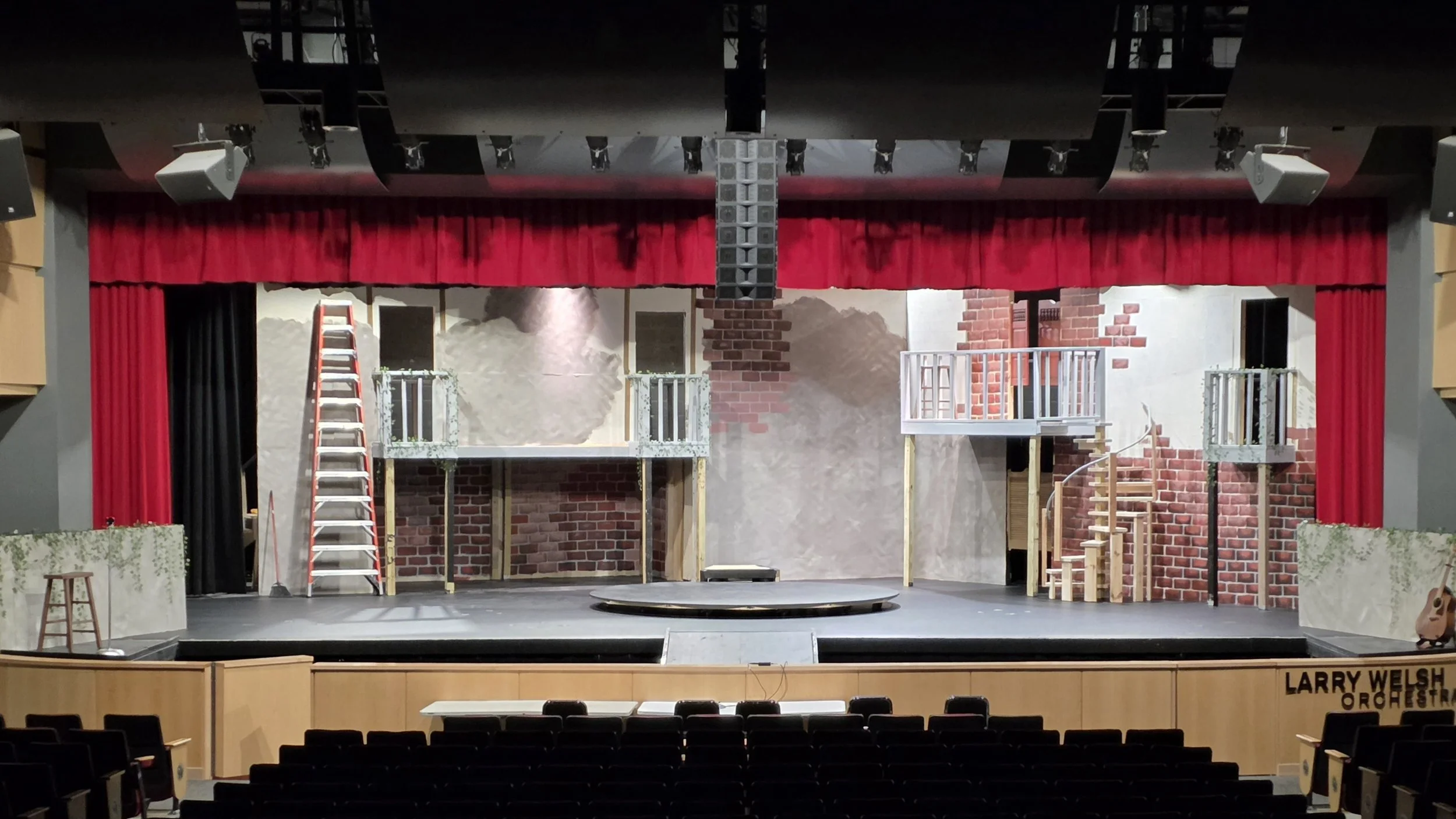
Primary Set Structure Complete, Finishing Begins
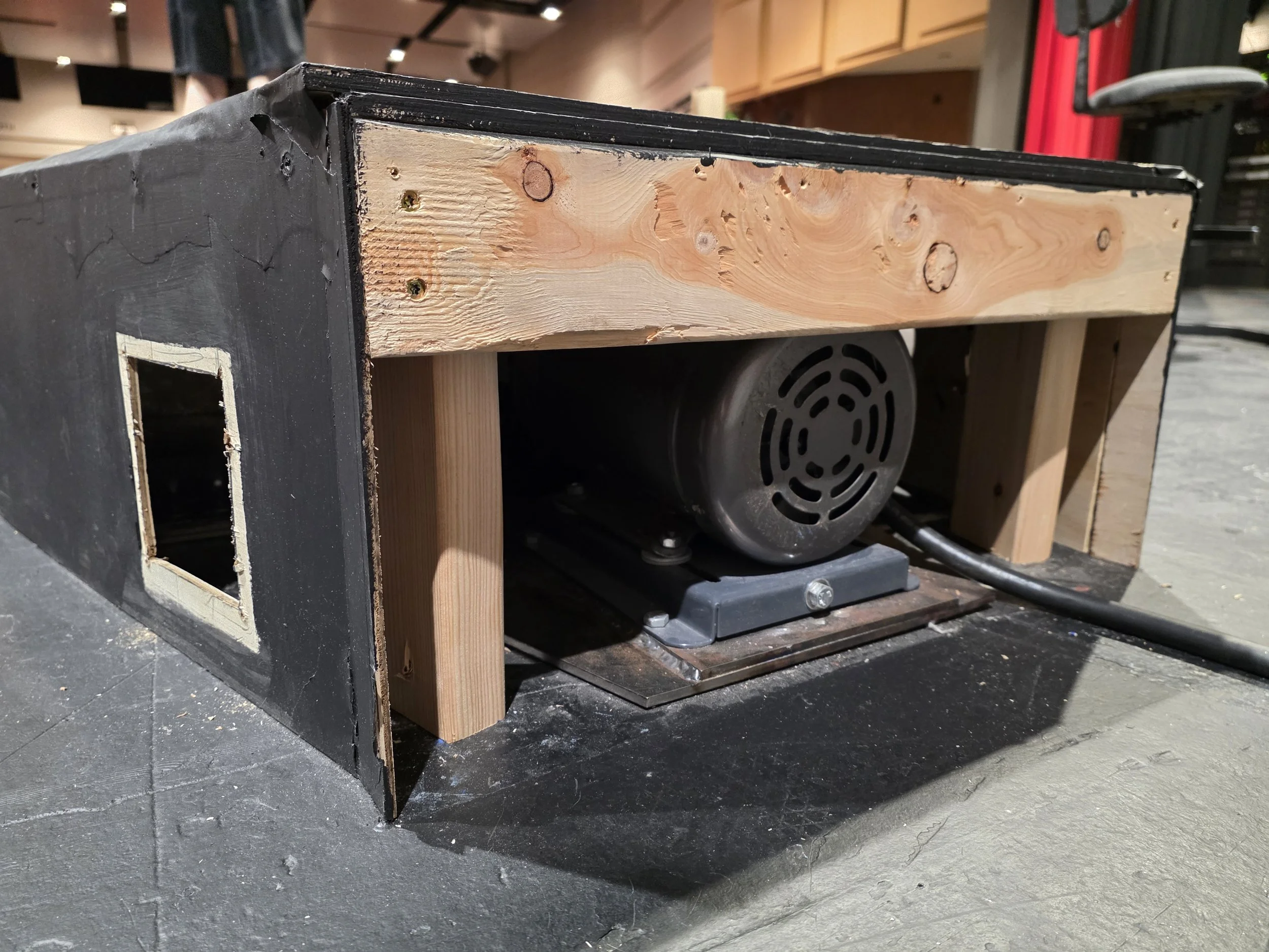
Installing Motor Cover and Air-Cooling System
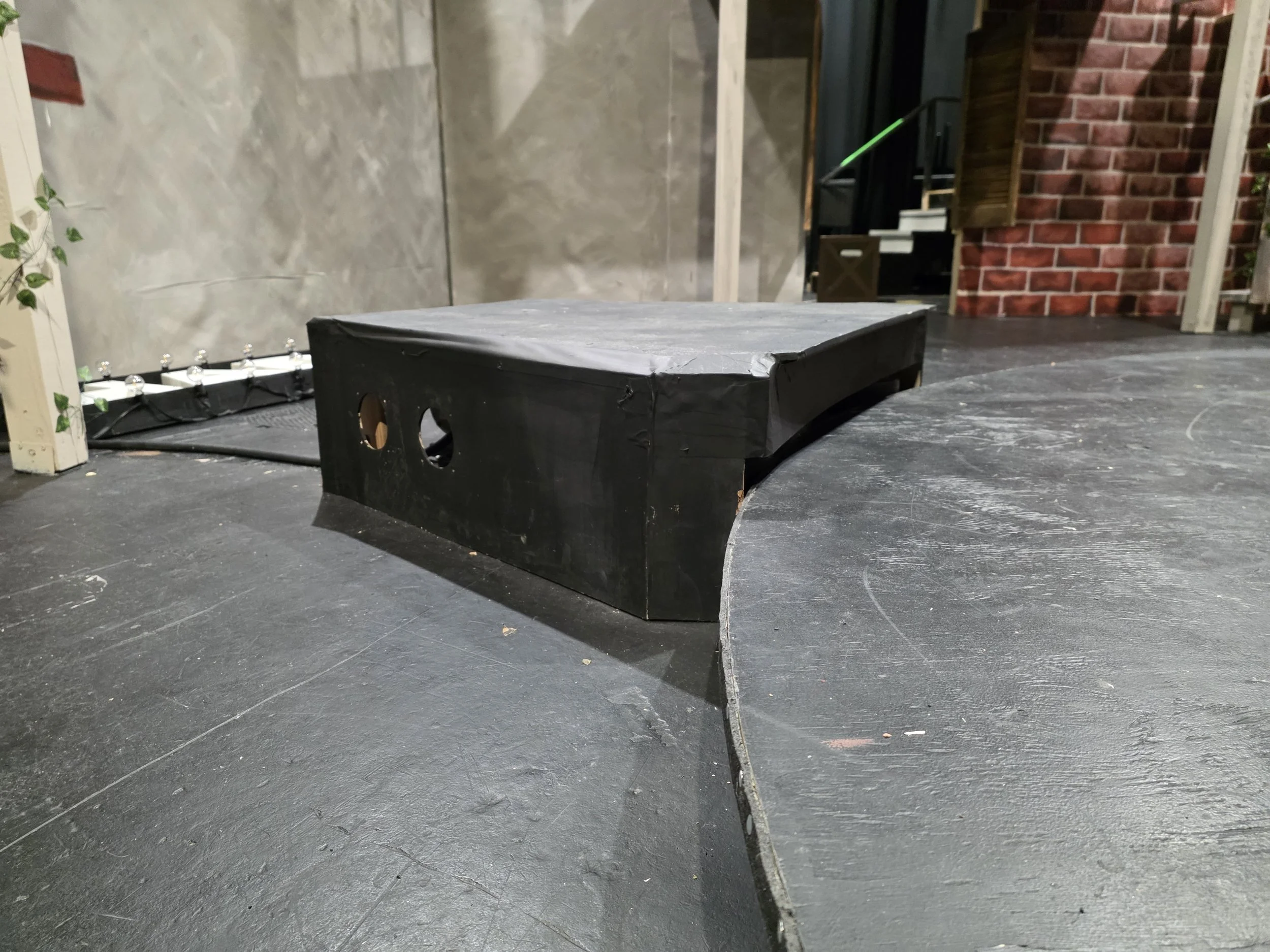
Turntable System Fully Integrated
FROM CAD TO STAGE
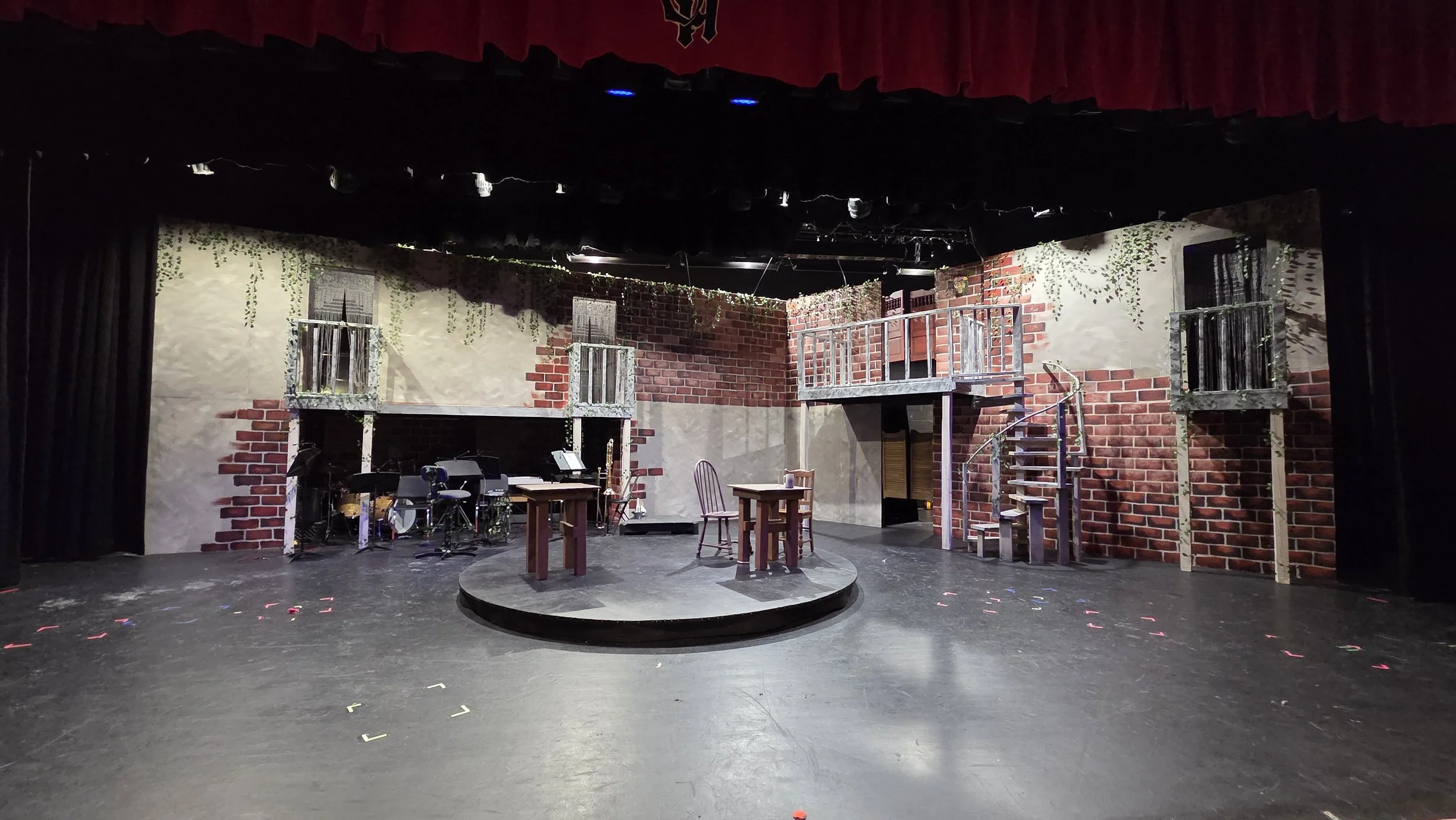
The final scenic environment remained remarkably close to the original digital model.
The completed set translated the major proportions, circulation paths, balconies, architectural openings, and central revolve from the design model into a full-scale performance environment.
PERFORMANCE
Once installed, the revolve became part of the choreography rather than simply a scenic effect. Variable speed and direction allowed the platform to support different moments throughout the production, while the stationary center created movement around performers or scenic elements that remained visually anchored.
After repeated mechanical revisions and break-in, the final system operated smoothly and quietly enough to function beneath dialogue, music, and choreography.
WHAT I LEARNED
This project fundamentally changed the way I approach design.
The finished revolve began as a circle on a hand-drawn floor plan. Making that circle actually rotate under a cast required me to move constantly between visual design, mechanical reasoning, fabrication, electronics, troubleshooting, and the realities of live performance.
CAD could establish geometry, but it could not predict every alignment problem, traction issue, vibration, control setting, or fabrication constraint. Each failure forced me to understand the system more deeply and make a more informed iteration.
By opening night, the project was no longer simply a set I had designed. It was a machine I had taken from concept through fabrication, testing, troubleshooting, and live operation.
That experience is ultimately what made the project important to me: the design was not finished when it looked right. It was finished when it worked.
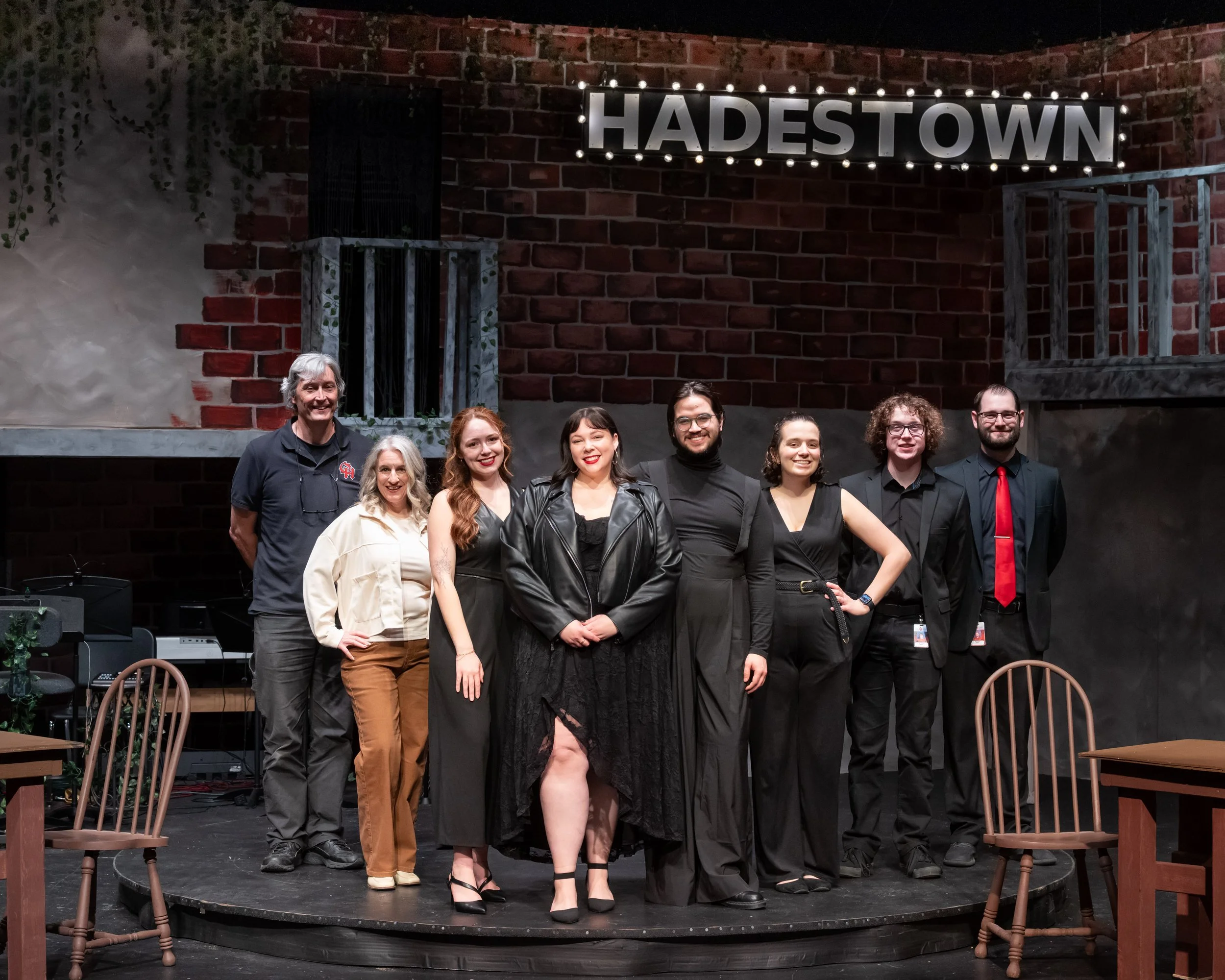
The Production Team that made it all happen (Left to Right):
Linus Ryland (Auditorium Manager), Amy Thompson (Pit Conductor), Elana Radigan (Choreographer), Josie Wass (Director), Nick Rohr (Assistant Director), Cassie Williams (Alumni Crew Lead), Corey Willett (Alumni Crew Lead), Josh Ward (Alumni Crew Lead)
Set Strike Timelapse
Nolan Philip’s (Student Automation Lead, Pit Performer) Trombone Solo
Marquee Sign Designed and Built by Me
Lighting Effect Designed and Programmed by Me